System for controlling starting and stopping of engine
- Summary
- Abstract
- Description
- Claims
- Application Information
AI Technical Summary
Benefits of technology
Problems solved by technology
Method used
Image

Examples
Example
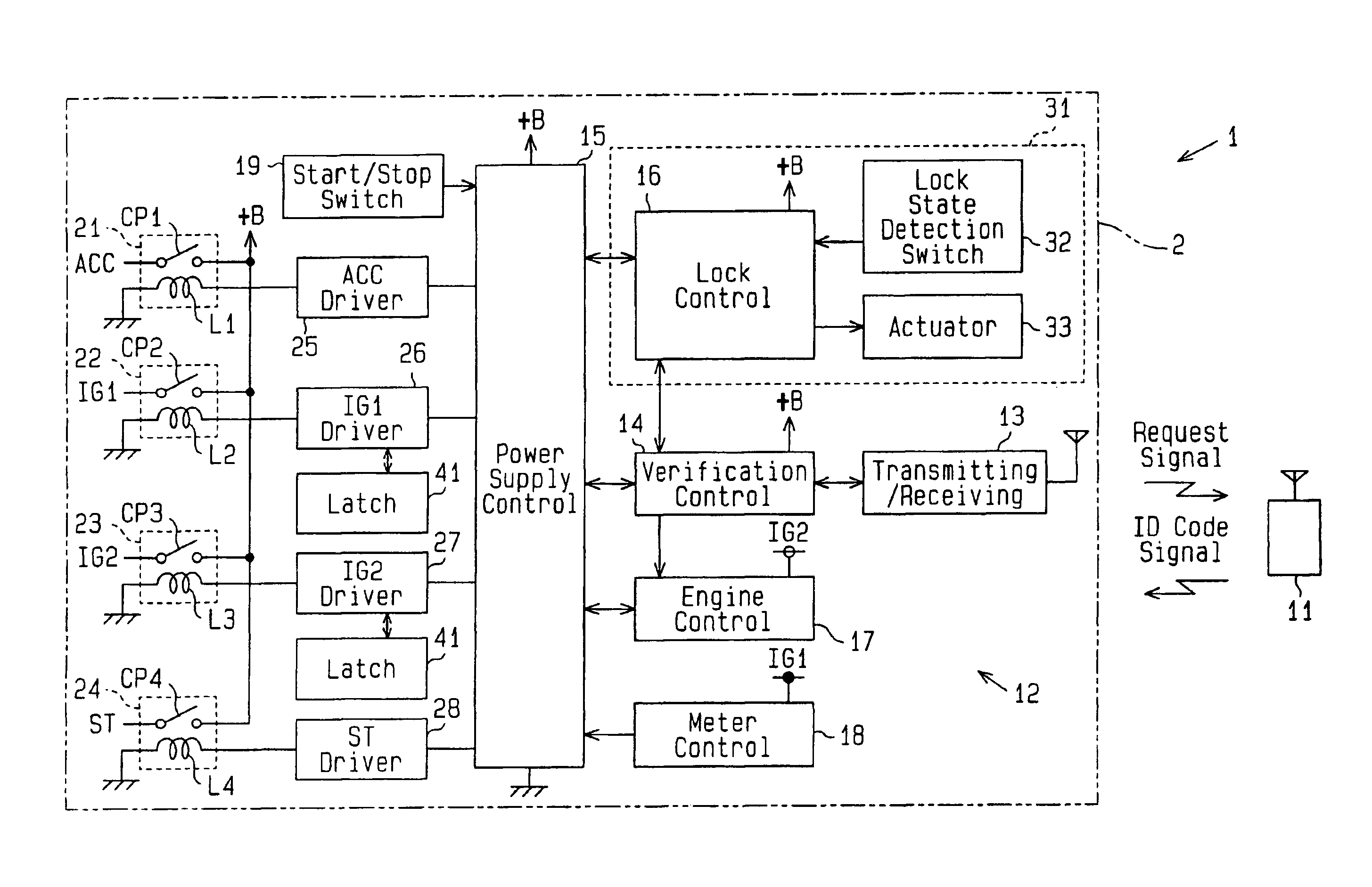
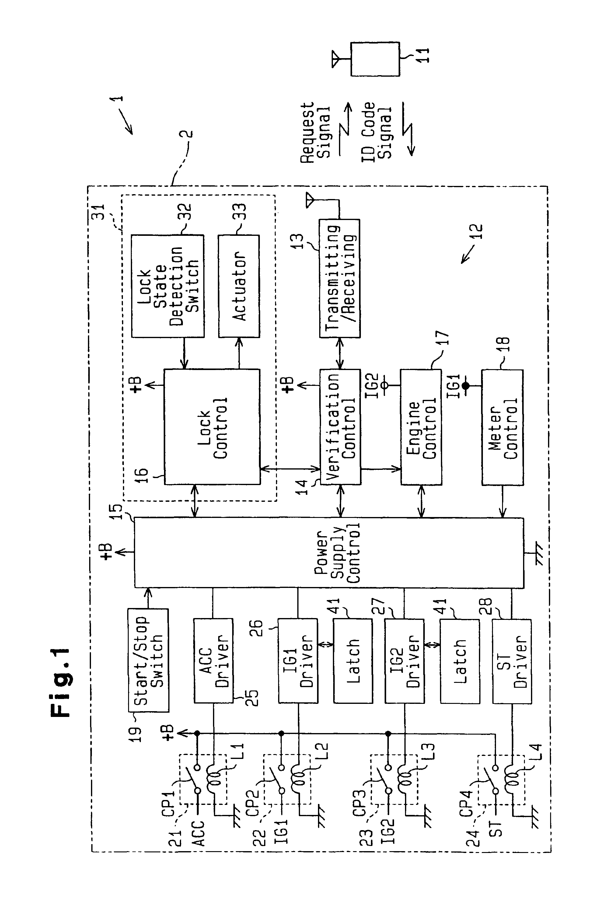
[0029]In the first embodiment, the lock release request signal, the lock release completion signal, the starting permission signal, the starting prohibition signal and the engine drive signal configure binary signal patterns having a predetermined bit number. When an abnormality, such as a short circuit or line breakage, occurs in the transmission path between the verification control unit 14 and each of the control units 14-17, the normal binary signal pattern is not configured. Each of the control units 14-17 determines whether the binary signal pattern is normal or abnormal to detect an abnormality in the transmission path and prevent erroneous functioning of the control unit 14-17.
[0030]The lock control unit 16 is electrically connected to a lock condition detection switch 32 and an actuator 33. The lock control unit 16, the lock condition detection switch 32 and the actuator 33 are part of a steering lock mechanism 31. The lock control unit 16 sends an unlock drive signal for r...
Example
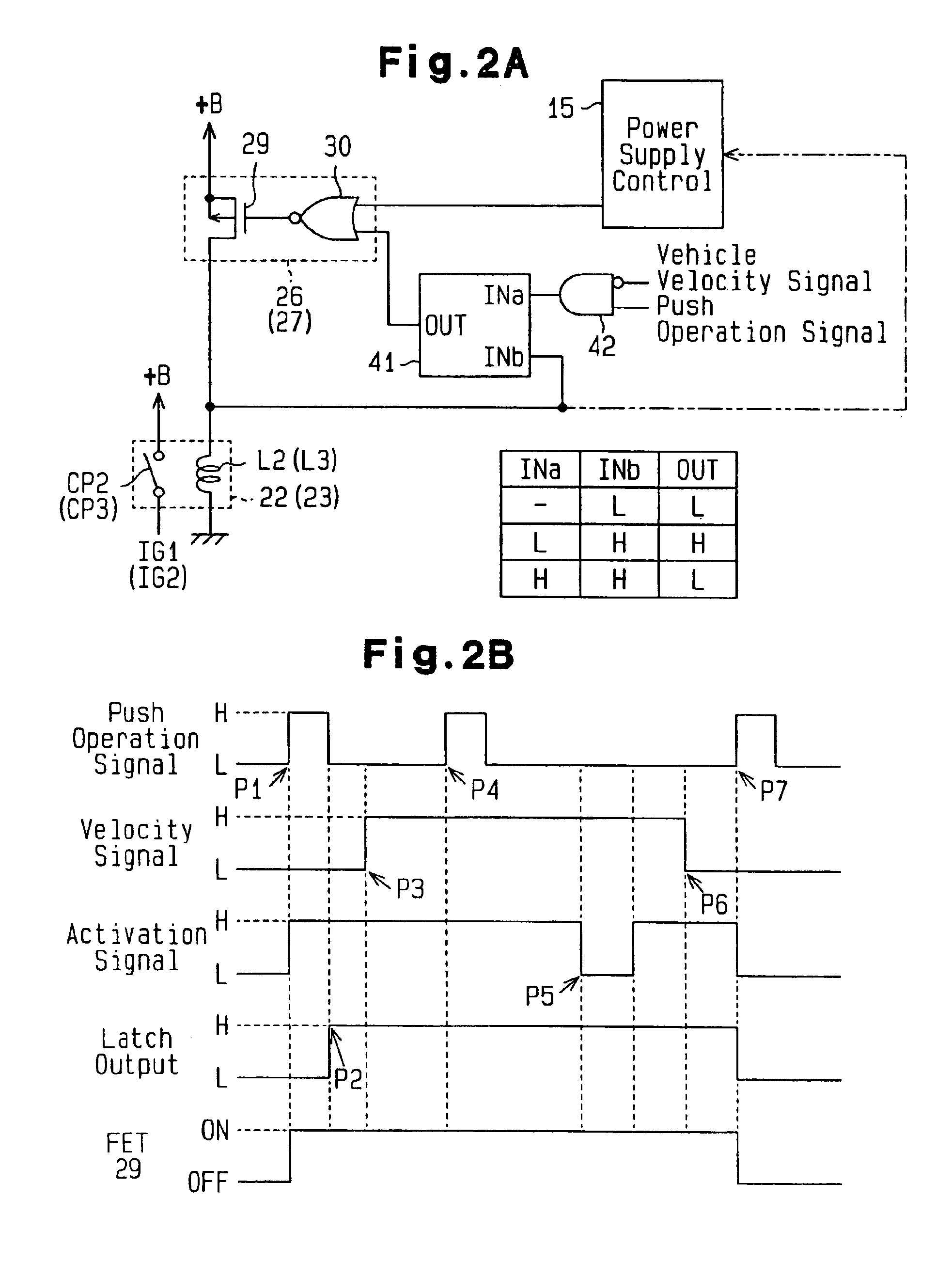
[0054]Next, a second embodiment of the present invention will be discussed with reference to FIGS. 3A and 3B. Differences from the first embodiment will be described. In the second embodiment, the IG1 driver circuit 26 and the IG2 driver circuit 27 differ from those in the first embodiment.
[0055]As shown in FIG. 3A, the driver circuits 26 and 27 each include a first p-channel MOSFET 29a, which functions as a first activation device, a second p-channel MOSFET 29b, which functions as a second activation device, and two inverter circuits 43 and 44.
[0056]The FETs 29a and 29b have source terminals connected to the positive terminal of the battery and drain terminals connected to the coils L2 and L3 of the corresponding relays 22 and 23. That is, the FETs 29a and 29b are connected in parallel to each other. The gate terminal of the first FET 29a is provided with an activation signal from the power supply control unit 15 via the inverter circuit 43. Therefore, the first FET 29a goes ON whe...
Example
[0068]Next, a third embodiment of the present invention will be discussed with reference to FIGS. 4A and 4B. Only the differences from the first embodiment will be described. The third embodiment differs from the first embodiment in the configuration of the AND circuit 42 in that the output signal of the latch circuit 41 is sent to the power supply control unit 15.
[0069]As shown in FIG. 4A, the AND circuit 42 has three input terminals and one output terminal. The AND circuit 42 has a first input terminal provided with the velocity signal, a second input terminal provided with the pushing operation signal, and a third input terminal provided with a shift position signal. The shift position signal is sent from a shift level position sensor (not shown). When the shift level is in a stop position, such as the parking (P) position or a neutral (N) position, the shift position signal is high. When the shift position is in a driving position, such as a drive (D) position or a reverse (R) p...
PUM
 Abstract
Description
Claims
Application Information
 - R&D Engineer
- R&D Manager
- IP Professional
- Industry Leading Data Capabilities
- Powerful AI technology
- Patent DNA Extraction
Browse by: Latest US Patents, China's latest patents, Technical Efficacy Thesaurus, Application Domain, Technology Topic.
© 2024 PatSnap. All rights reserved.Legal|Privacy policy|Modern Slavery Act Transparency Statement|Sitemap