Power fastening tool

Active Publication Date: 2005-05-26
MATSUSHITA ELECTRIC WORKS LTD
View PDF1 Cites 18 Cited by
  • Summary
  • Abstract
  • Description
  • Claims
  • Application Information

AI Technical Summary

Benefits of technology

[0025] It is possible that the power fastening tool further comprises a judging condition selector by which the user can optionally select alternative of the above-mentioned two condition

Problems solved by technology

The first conventional power fastening tool which stops the driving of the motor corresponding to the impact number and the second conventional power fastening tool which stops the driving of the motor corresponding to the rotation angle respectively have a disadvantage that a large difference may occur between a desired torque and the actual torque for fastening the fastening member.
The difference causes loosening of the fastening member due to insufficient torque when the actual torque is much smaller than the desired torque.
Alternatively, the difference causes to damage the elements to be fastened by the screw or the bolt or to damage a head of the fastening member due to superfluous torque when the actual torque is much larger than the desired torque.
On the other hand, the third conventional power fastening tool which stops the driving of the motor corresponding to the actual torque for fastening the

Method used


Image

  • Power fastening tool
  • Power fastening tool
  • Power fastening tool

Examples


Example

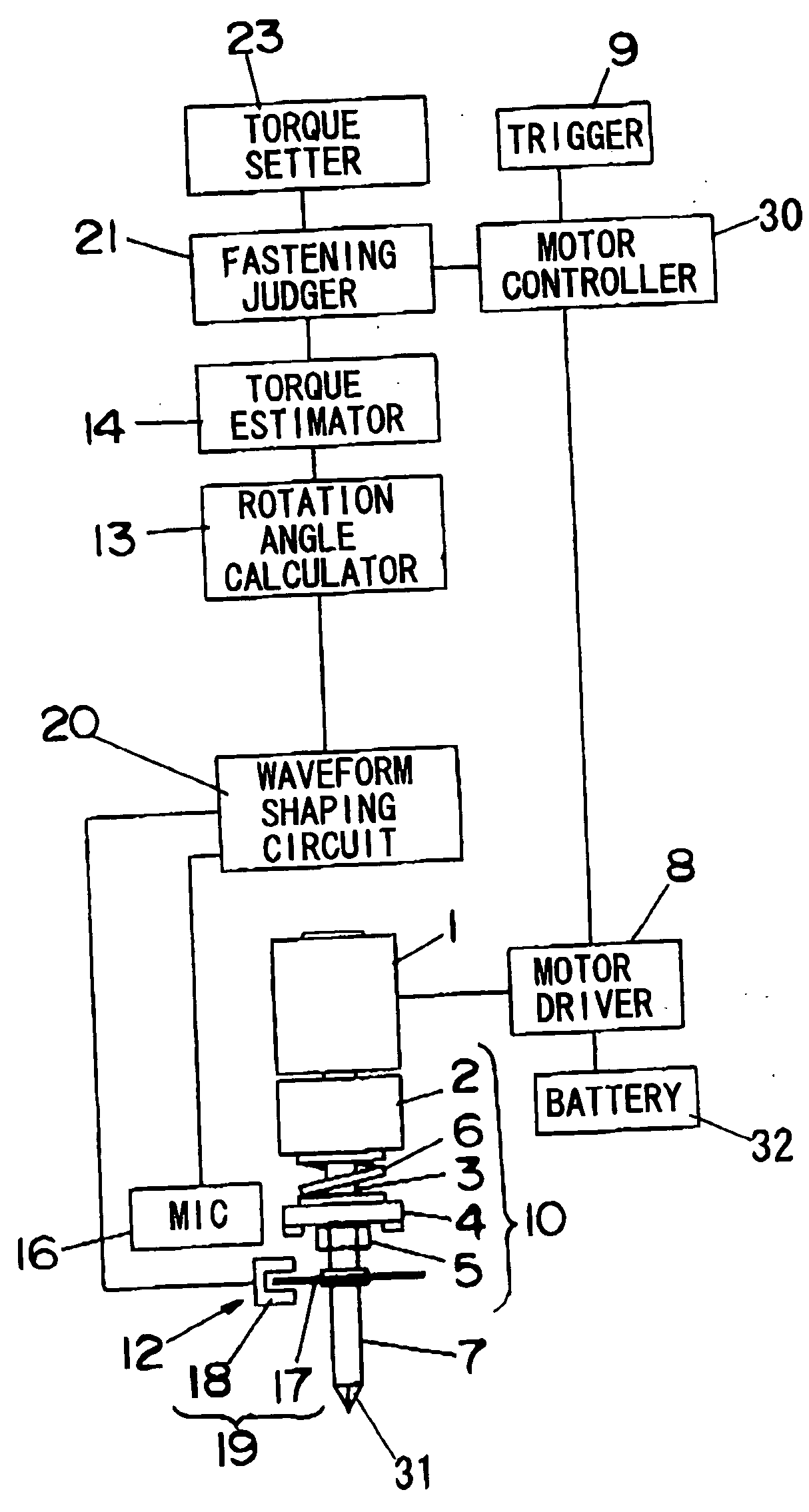
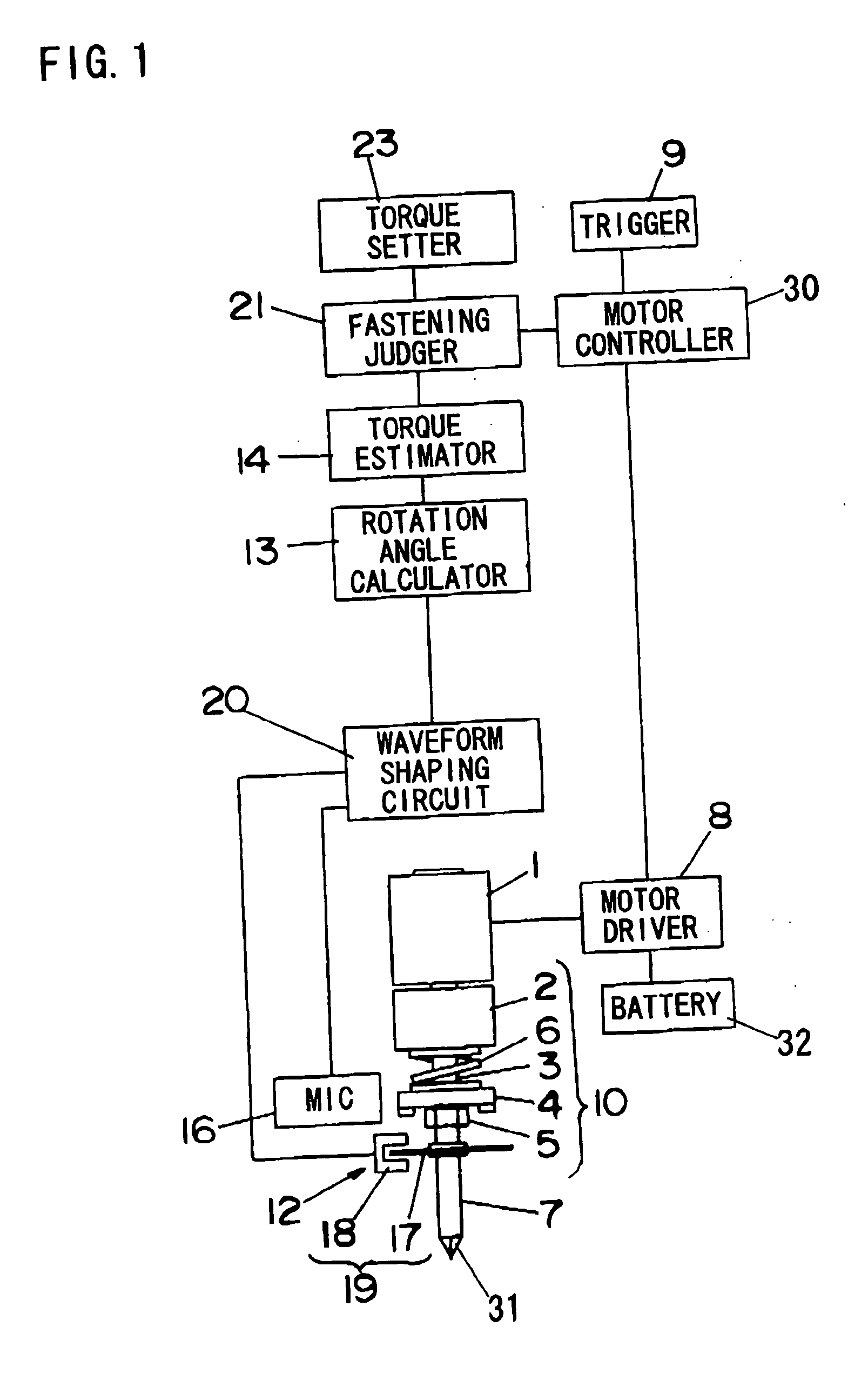
[0050] A power fastening tool in accordance with a first embodiment of the present invention is described. FIG. 1 shows a configuration of a power impact tool used for fastening a fastening member such as a screw or a bolt as an example of the power fastening tool in the first embodiment.

[0051] The power impact tool comprises a motor 1 for generating a driving force, and a power transmitter 10 for transmitting the driving force of the motor 1 to an output shaft 7. A bit 31 for fastening or loosening a fastening member such as a screw or a bolt is detachable fitted to a top end of the output shaft 7. The power transmitter 10 further comprises a reducer 2 for reducing rotation speed of a shaft of the motor 1 (hereinafter abbreviated as rotation speed of the motor 1), a driving shaft 3 connected to the reducer 2 and rotated by the driving force of the motor 1, a hammer 4 engaged with the driving shaft 3 via a spline bearing, an anvil 5 engaged with the driving shaft 3 with a clutch me...

Example

Second Embodiment

[0077] A power fastening tool in accordance with a second embodiment of the present invention is described. The configuration of the power fastening tool in the second embodiment is essentially the same as that of the above-mentioned first embodiment except the judgment of the complete fastening of the fastening member. Thus, only the different points of the power fastening tool in the second embodiment from that in the first embodiment are described. The power impact tool illustrated in FIG. 1 is used as an example of the power fastening tool in the second embodiment. The power impact tool illustrated in FIG. 7 or 8, however, can be used as an example of the power fastening tool in the second embodiment. The same goes for the other embodiments.

[0078]FIG. 9 shows a basic flow of the fastening operation of the fastening member in the second embodiment, in which the fastening operation of the fastening member is completed when a sum Σ(ΔΔT) of the values of the torqu...

Example

Third Embodiment

[0085] In the third embodiment, the fastening judger 21 has two conditions for judging the complete fastening of the fastening member corresponding to the kinds of work operation.

[0086]FIG. 12 shows an example of a front view of the torque setter 23. In comparison with the example shown in FIG. 3, the torque setter 23 further has a work selection switch 33 for selecting a kind of the work operation, which outputs a signal corresponding to a selection by the user. In this example, the work selection switch 33 can select between the woodwork and the metalwork.

[0087]FIG. 13 shows a basic flow of the fastening operation of the fastening member in the third embodiment, in which the fastening operation of the fastening member is completed when the value of the estimated torque T for fastening the fastening member becomes larger than the lower limit value T1 of the torque and the value of the torque variation ratio ΔΔT varies from positive to negative in case of the wood...


PUM


Abstract

In a power fastening tool for fastening a fastening member such as a screw or a fastening member, malfunction that driving of a motor is stopped before the fastening member is fastened completely can be prevented. A fastening judger judges that the fastening operation is completed when a value of an estimated torque T for fastening the fastening member becomes larger than a predetermined lower limit value T1 previously set by a user and a value of a torque variation ratio ΔΔT varies from positive to negative. Thus, it is possible to prevent malfunction for stopping driving of a motor even when the value of the torque variation ratio ΔΔT varies from positive to negative due to trouble before the vale of the estimated torque T becomes larger than the lower limit value T1.

Description

BACKGROUND OF THE INVENTION [0001] 1. Field of the Invention [0002] The present invention relates to a power fastening tool such as an impact driver or an impact wrench used for fastening a fastening member such as a screw or a bolt. [0003] 2. Description of the Related Art [0004] Conventionally, a power fastening tool used for fastening a fastening member such as a screw or a bolt utilizing driving force of a motor has a function automatically stopping driving of the motor when a torque necessary for fastening the fastening member reaches to a predetermined value due to the fastening member is fastened completely. [0005] In a first conventional power fastening tool such as an impact wrench used for fastening a fastening member, for example, shown in publication gazette of Japanese Patent Application 4-322974, a number of impact of a hammer is sensed and driving of a motor is automatically stopped when the number of impact reaches to a predetermined reference number. [0006] In a sec...

Claims


Application Information

Patent Timeline
IPC IPC(8): B25B23/14B25B21/02B25B23/147G05D17/02
CPCB25B21/02G05D17/02B25B23/1475
Inventor KAWAI, KOZOSAINOMOTO, YOSHINORIMATSUMOTO, TATSUHIKOARIMURA, TADASHIOHASHI, TOSHIHARUMIYAZAKI, HIROSHISHIMIZU, HIDENORISAWANO, FUMIAKI
Owner MATSUSHITA ELECTRIC WORKS LTD
Why Eureka
Try Eureka