
Sub-packet insertion for packet loss compensation in voice over IP networks

Active Publication Date: 2005-05-31
MITEL
View PDF17 Cites 10 Cited by
  • Summary
  • Abstract
  • Description
  • Claims
  • Application Information

AI Technical Summary

Benefits of technology

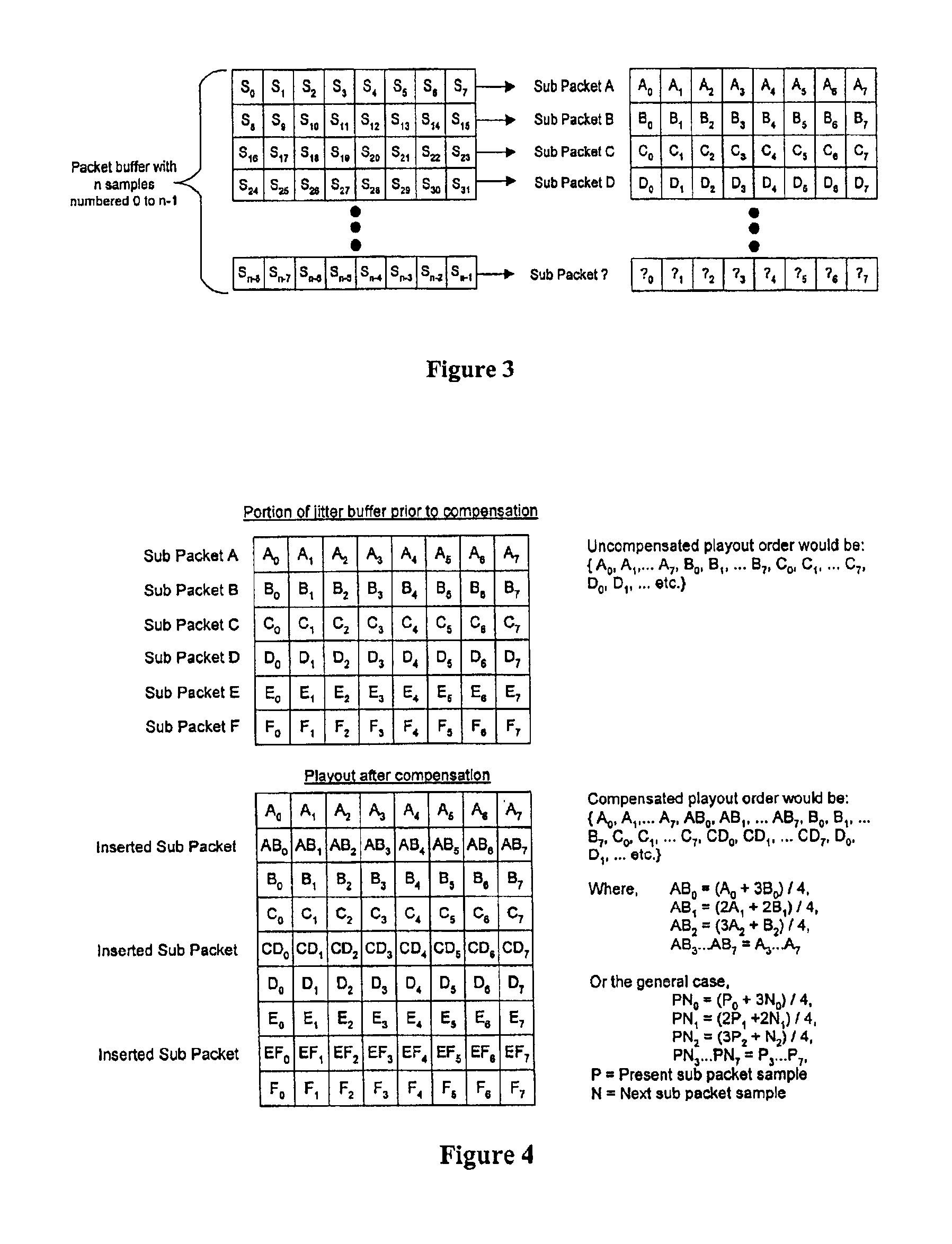
[0009]According to the present invention, a method is provided for packet loss compensation in real time voice over IP applications. The method of the invention allows a receiving endpoint to dynamically detect and recover from packet loss with minimal processing overhead. Specifically, a hybrid method of packet loss compensation is provided in accordance with which only small portions of the jitter buffer (referred to herein as sub packets) are replayed at specific times to minimize the negative effects on voice quality. The inventive method inserts the replayed portions to compensate for packet loss in a way that results in only a relatively low processing burden.

Problems solved by technology

The transmission of voice and audio data over IP networks presents some inherent challenges regarding end to end quality of service.
Specifically, packet loss, packet delays and packet jitter are characteristics that can significantly impact voice quality.
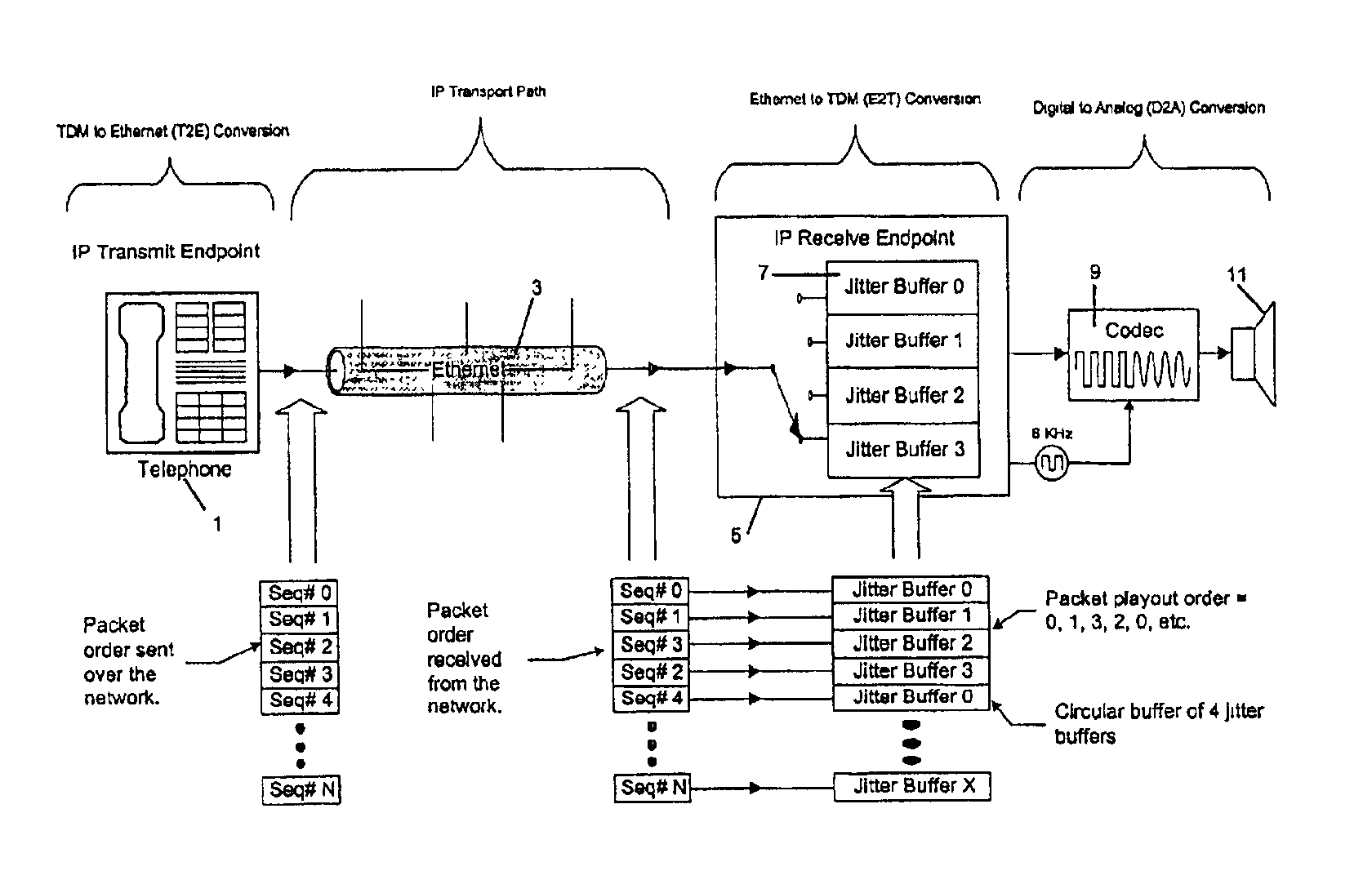
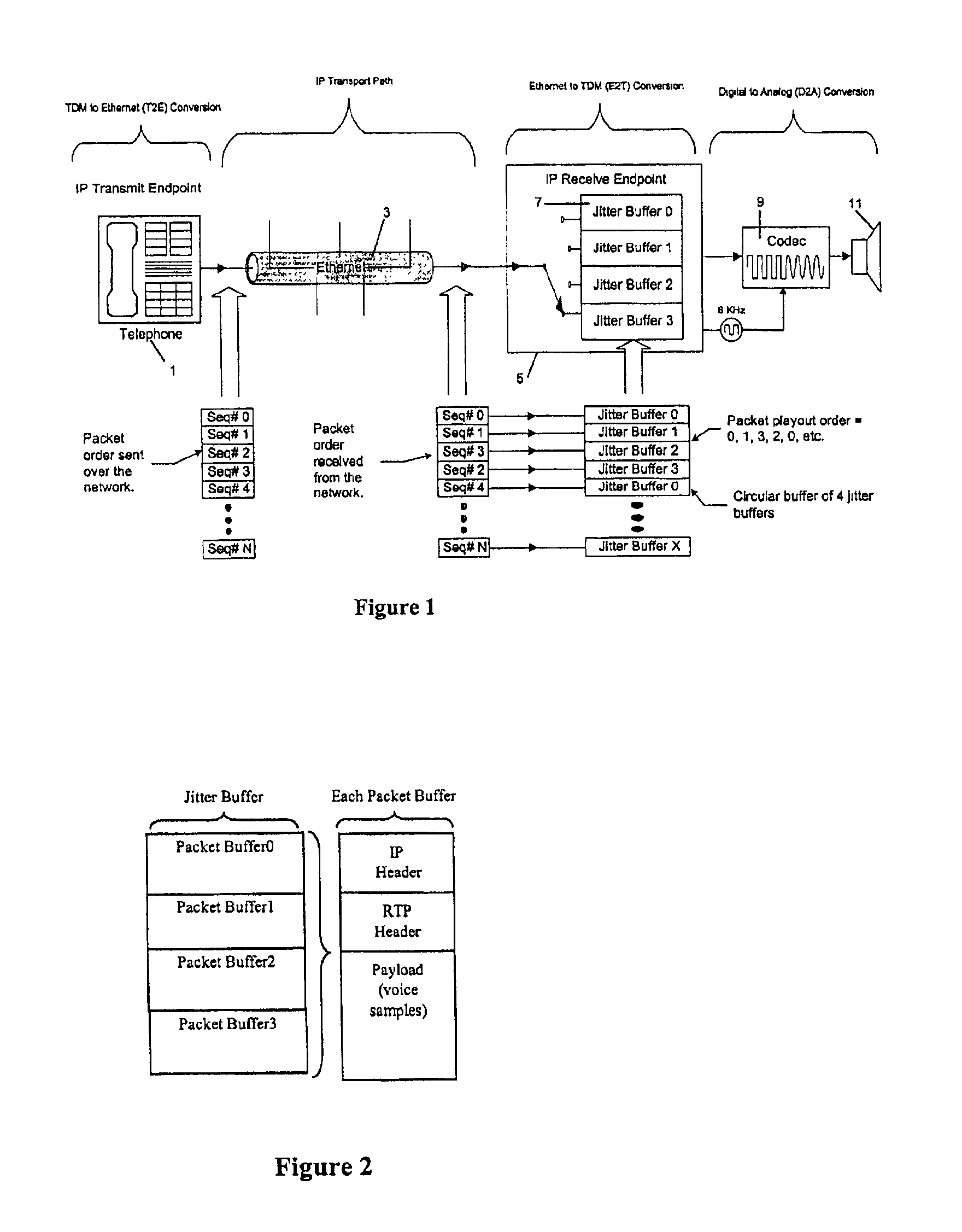
From an endpoint's (e.g. phone) perspective on an IP network, packet loss occurs in an arbitrary, unpredictable fashion.
Packet loss is out of the endpoint's control and typically occurs due to a collision or some network overload (e.g. in a router or gateway).
Since the packet loss can occur in the physical implementation of the network (e.g. collisions in cables) there is no guaranteed mechanism to inform the receiver when a packet is missing.
Also, once lost, the packet is not re-transmitted since the associated delay in retransmission is prohibitive in real time telephony applications.
The challenge in this respect is to adequately reconstruct the original signal and maintain a sufficient level of voice quality.
As a result of variable queuing delays and variable routing paths, sequential periodic packets sent from a source can arrive out of order and with substantial delay and jitter at the destination endpoint.
Unfortunately such a buffer increases the nominal delay of the audio stream depending on its size, and as such must be minimized since audio delay has its own negative effect on voice quality.
Simple replaying of a previous packet is computationally trivial yet often yields unsatisfactory results since voice quality dramatically suffers as packet loss increases.
A variation of this scheme is to replace the lost packet with an idle or zeros packet but this too is quite noticeable under even marginal packet loss.
Both methods have an undesirable side effect of causing a frequency shift of the signal due to the change in sample rate.
However, under conditions of packet loss, small adjustments do not provide an adequate rate of compensation.
Unfortunately in voice conversations silence periods are often very small (between words) and they cannot be guaranteed during the time frame of a typical jitter buffer.
Furthermore, silence detection imposes an additional processing burden when compared to the other prior art methods of compensation.

Method used


Image

  • Sub-packet insertion for packet loss compensation in voice over IP networks
  • Sub-packet insertion for packet loss compensation in voice over IP networks
  • Sub-packet insertion for packet loss compensation in voice over IP networks

Examples


Embodiment Construction

[0015]The basic features of any voice over IP implementation are a transmitting and receiving endpoint separated by an IP network. The IP network consists of various interconnected elements such as hubs, routers and gateways. From an endpoint perspective, however, the interface is simply a connecting IP cable which can be viewed as a dedicated connection from transmitter to receiver.

[0016]Thus, as shown in FIG. 1, a transmitting endpoint 1 on the IP network simply accumulates samples from its Analog to Digital process (TDM to Ethernet (T2E)) into a packet or payload buffer within the endpoint 1, according to a sequential order. Once the buffer is fall the endpoint transmitter wraps a packet header around the payload and transmits this across the network 3 with appropriate addressing and sequence information in the header, as is well known in the art. The routing information in the header describes the final destination and is attached to each and every packet (e.g. Seq# 0, Seq# 1, e...


PUM


Abstract

A method of compensating within a receiving endpoint for lost audio packets transmitted across an IP network, comprising the steps of storing a packet buffer of samples as a plurality of sub packets within a jitter buffer, inserting at least one interpolated sub packet between successive sub packets in the buffer, and playing out the sub packets from the buffer, such that only small portions of the jitter buffer are replayed at specific times to minimize the negative effects on voice quality. The inventive method inserts the replayed portions to compensate for packet loss in a way that results in only a relatively low processing burden.

Description

FIELD OF THE INVENTION[0001]This invention relates in general to digital signal transmission, and more particularly to a sub-packet insertion method for packet loss compensation method in voice over IP (VOIP) networks.BACKGROUND OF THE INVENTION[0002]The transmission of voice and audio data over IP networks presents some inherent challenges regarding end to end quality of service. Specifically, packet loss, packet delays and packet jitter are characteristics that can significantly impact voice quality.[0003]From an endpoint's (e.g. phone) perspective on an IP network, packet loss occurs in an arbitrary, unpredictable fashion. Packet loss is out of the endpoint's control and typically occurs due to a collision or some network overload (e.g. in a router or gateway). Since the packet loss can occur in the physical implementation of the network (e.g. collisions in cables) there is no guaranteed mechanism to inform the receiver when a packet is missing. Therefore, sequence numbers are us...

Claims


Application Information

Patent Timeline
IPC IPC(8): G10L19/00H04M1/253H04L1/00H04L29/06H04H1/02H04H1/10H04L12/56G10L19/005H04H20/82H04L12/861
CPCG10L19/005H04L1/00H04M1/2535H04L49/90H04L29/06H04L9/40H04L49/9023
Inventor BASTIN, ROGER
Owner MITEL
Learn More