

Method for evaluating logic functions by logic circuits having optimized number of and/or switches
- Summary
- Abstract
- Description
- Claims
- Application Information
AI Technical Summary
Benefits of technology
Problems solved by technology
Method used
Image

Examples
Embodiment Construction
[0015]Reference will now be made in detail to the presently preferred embodiments of the invention, examples of which are illustrated in the accompanying drawings.
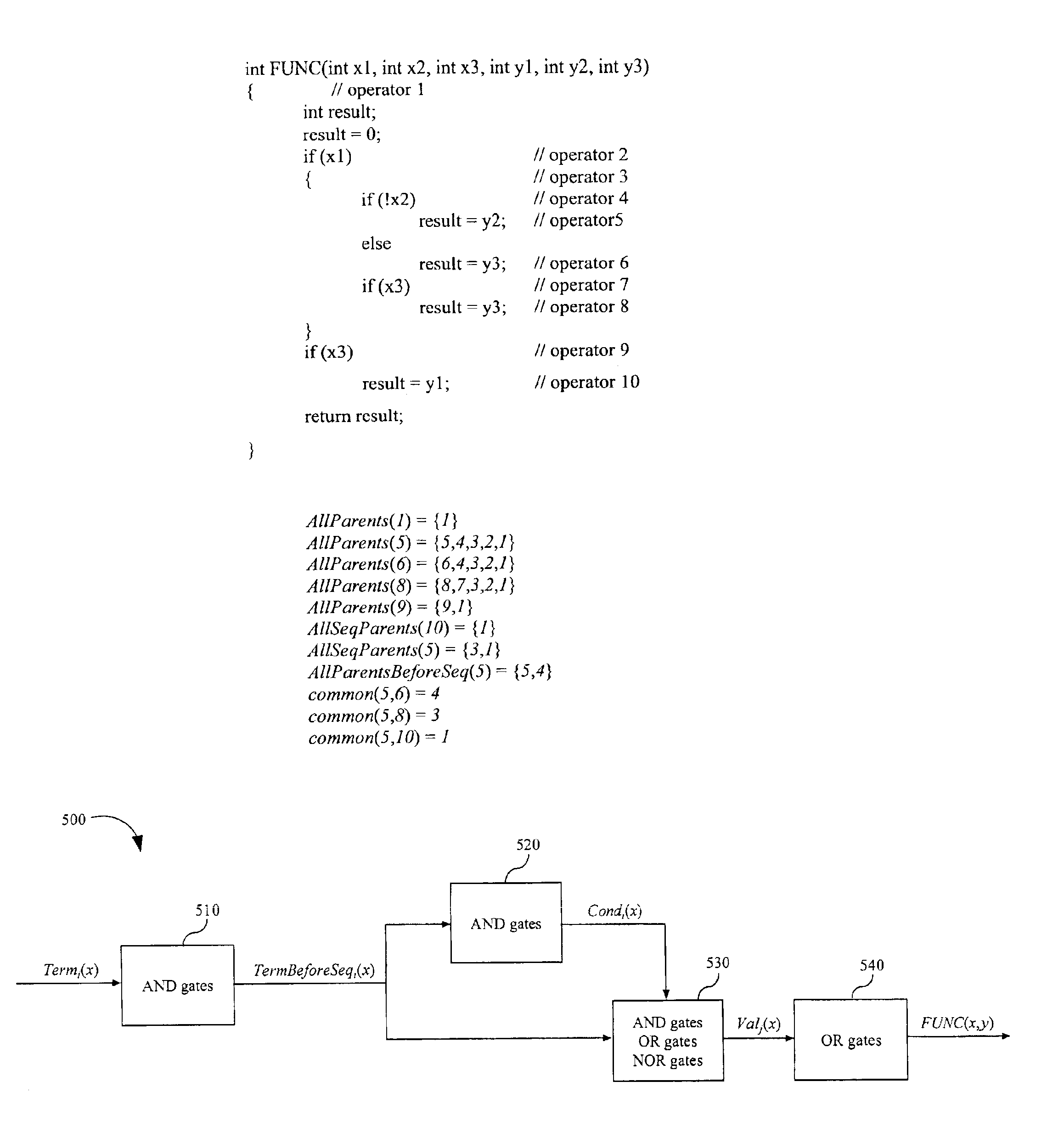
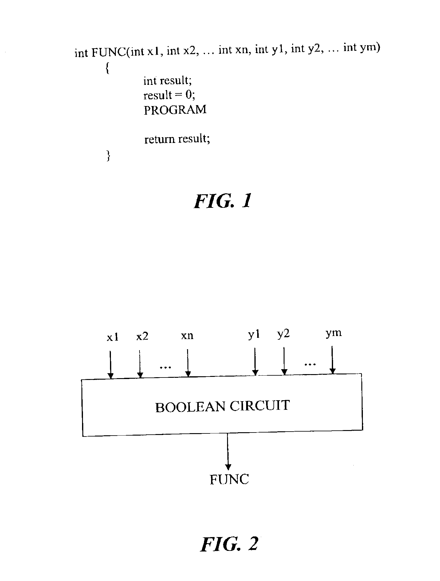
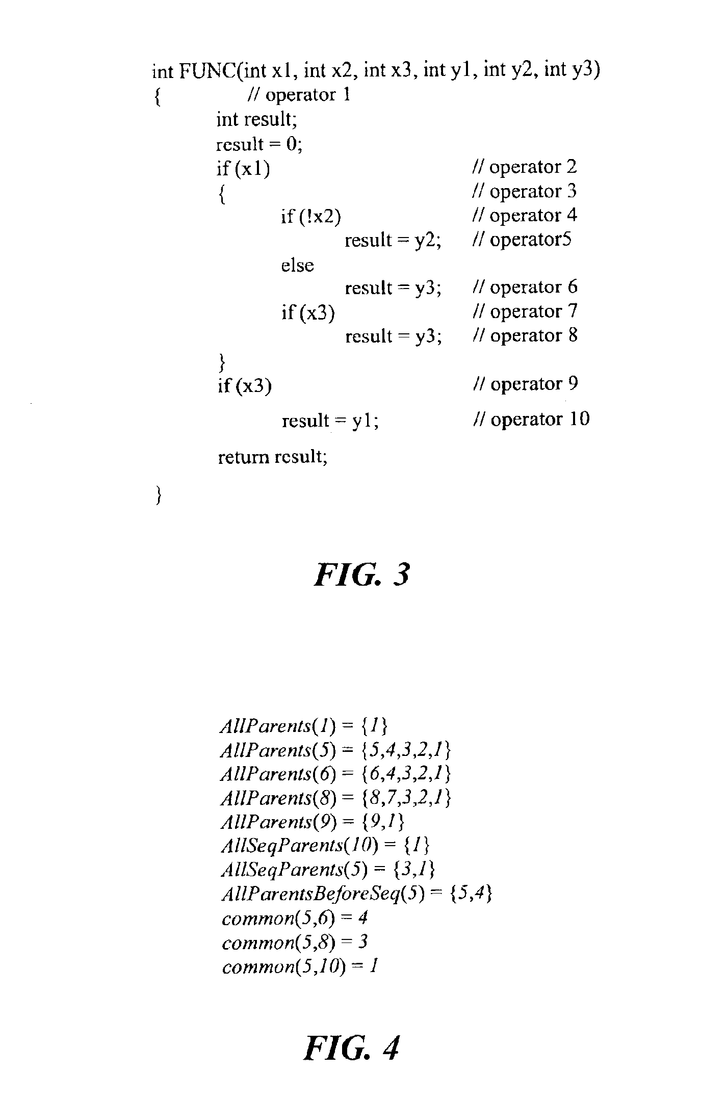
[0016]As shown in FIG. 1, an exemplary logic function FUNC is determined by means of C++ functions. Inputs x1, x2, . . . , xn, y1, y2, . . . , ym, n≧1, m≧1 may take values of only 0 (low) and 1 (high). Inputs x1, x2, . . . ,xn may be called control inputs, and inputs y1, y2, . . . , ym may be called data inputs.
[0017]In FIG. 1, the C++ program PROGRAM may include operators of the following three types:[0018]1) IF-operators, which may be defined as follows:[0019]iƒ(xi) positive_operator else negative_operator or[0020]if(xi) negative_operator else positive_operator
( represents a NOT function). It should be noted that the else option may be absent without departing from the spirit and scope of the present invention.[0021]2) EQ-operators, which may be defined as follows:[0022]result=yi;[0023]3) SEQ-operators, which may be defi...
PUM
 Abstract
Description
Claims
Application Information