Upper body support device

a support device and upper body technology, applied in the field of support devices, can solve the problems of not being able to properly support the spinal cord and the shoulders of users, and not being able to address the proper positioning and support of the spinal cord, especially in the shoulder area

Inactive Publication Date: 2005-06-07
GEISERT CHRISTOPHER
View PDF14 Cites 23 Cited by
  • Summary
  • Abstract
  • Description
  • Claims
  • Application Information

AI Technical Summary

Problems solved by technology

However, these prior art devices are typically designed for entry positioning and supporting the head and neck region of a user and have heretofore not been suitable for positioning the spinal cord and shoulders of a user, especially with respect to the hea

Method used


Image

  • Upper body support device
  • Upper body support device

Examples


Embodiment Construction

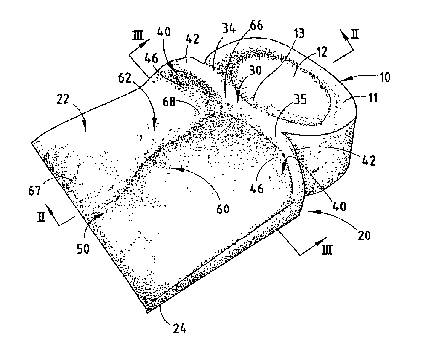
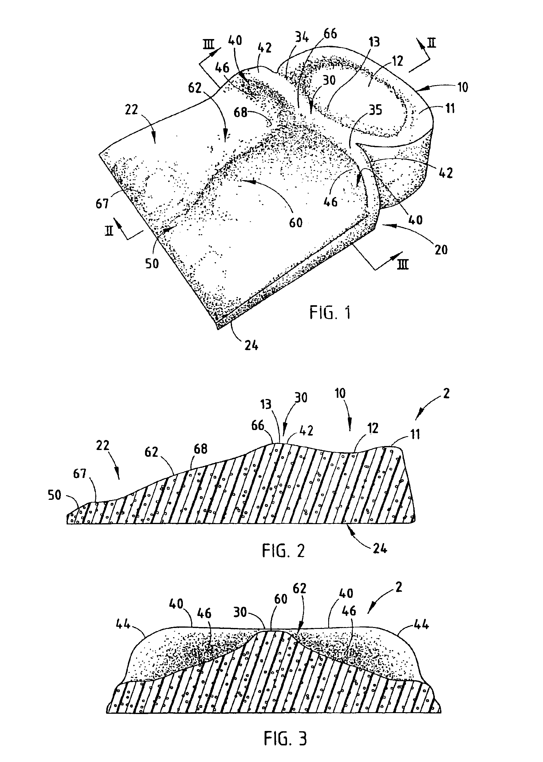
[0010]In a first embodiment (FIG. 1), the upper body support device 2 includes a first side 22 comprising a head support portion 10 and a thoracic support portion 20, and generally planar second side 24. Thoracic support portion 20 further includes cervical region 30, shoulder region 40, lumbar region 50 and spinal region 60. Further, spinal region 60 includes a convex arcuatcly shaped portion or region 62 which supports a user's spinal area such that the user's head, neck and shoulders are all optimally positioned to prevent and / or treat common back problems as well as promote better sleep.

[0011]Head support portion 10 is generally oval in geometry and includes a generally planar surface 11. However, head support 10 may take on various configurations and / or shapes without departing from the inventive concept. In the illustrated embodiment head support 10 and more appropriately planar surface 11 includes a concave surface 12 wherein the users head may be comfortably positioned there...


PUM


Abstract

An upper body device includes a thoracic support region comprising a spinal region having a convex arcuate section on an upper surface thereof to properly position a user's shoulders with respect to the users head, cervical and spinal region.

Description

BACKGROUND OF THE INVENTION[0001]The present invention relates to devices used to prevent, treat or otherwise aid in the relief of back problems. More particularly, the present invention relates to a support device used for the treatment or prevention of back problems.[0002]There are a number of prior art beds, pillows, cushioning devices and platforms for supporting the head and / or body of a person for various therapeutic and recreational purposes. However, these prior art devices are typically designed for entry positioning and supporting the head and neck region of a user and have heretofore not been suitable for positioning the spinal cord and shoulders of a user, especially with respect to the head and neck region. Therefore, among the various types of devices that have been designed to elevate and / or position the head and neck of a user, none address the proper positioning and support of the spinal cord, especially with respect to the shoulder area.[0003]Therefore, there remai...

Claims


Application Information

Patent Timeline
IPC IPC(8): A47C20/02A47C20/00A47G9/10A61F13/12
CPCA47G9/10A61F13/128A61F5/56A47G9/1081
Inventor GEISERT, CHRISTOPHER P.
Owner GEISERT CHRISTOPHER
Why Eureka
Try Eureka