Apparatus and method for cleaning an air filter unit

US6902592B2Inactive Publication Date: 2005-06-07UNITED AIR SPECIALISTS

Image

  • Apparatus and method for cleaning an air filter unit
  • Apparatus and method for cleaning an air filter unit
  • Apparatus and method for cleaning an air filter unit

Examples


Embodiment Construction

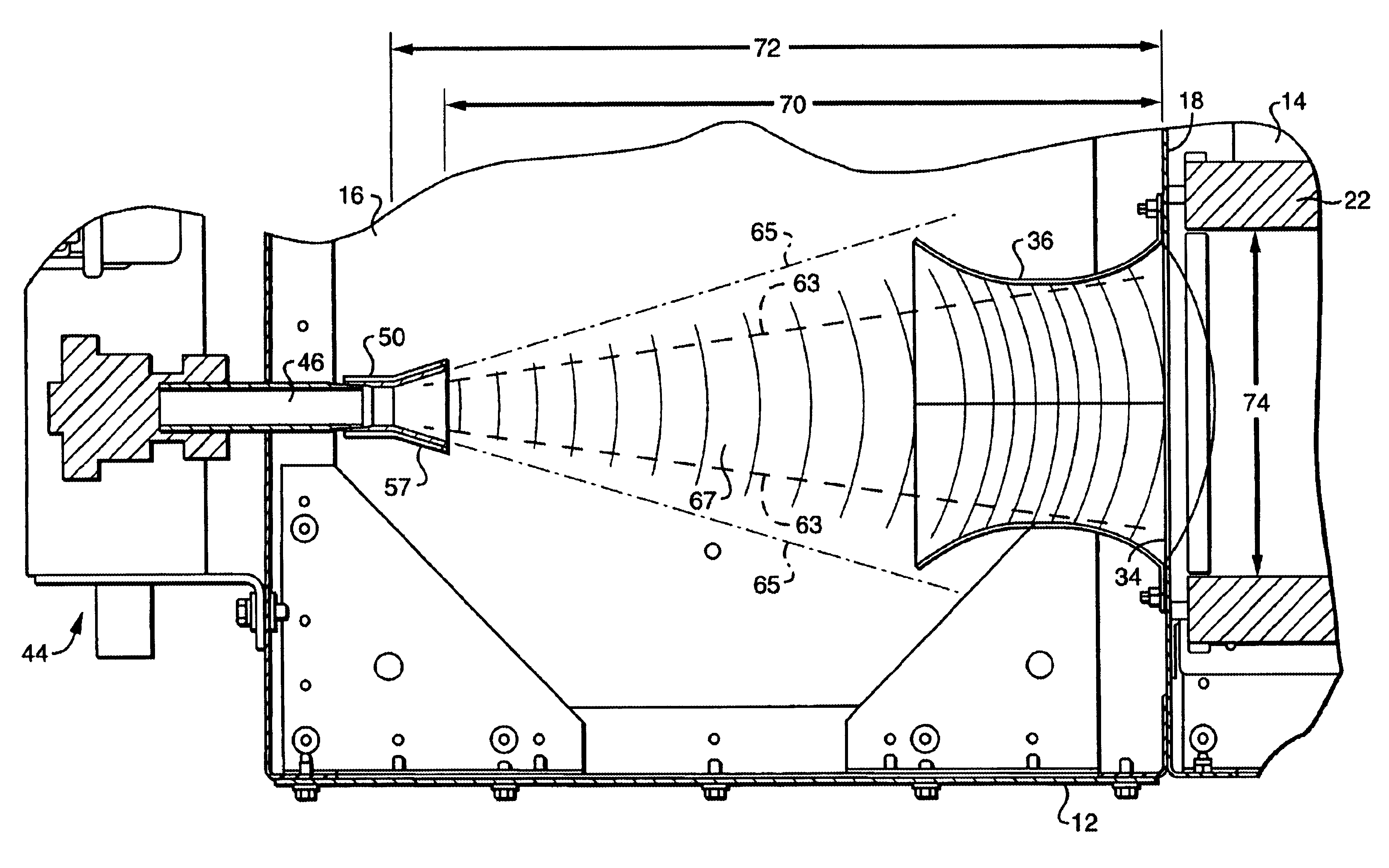
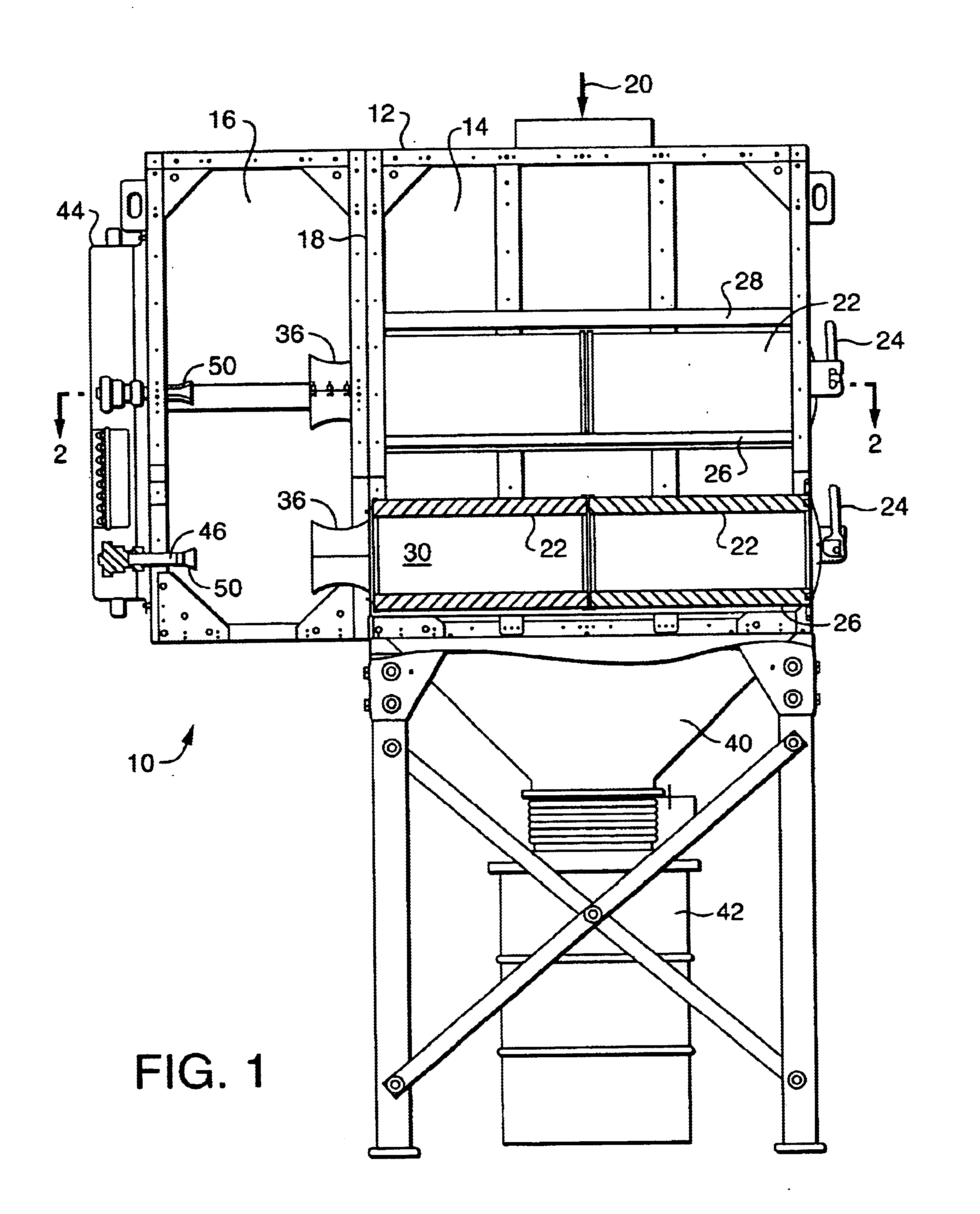
[0019]Referring now to the various figures of the drawing, and first to FIG. 1, therein is shown at 10 a partially cut away side view of an air filtration system according to a preferred embodiment of the present invention. The system includes a housing 12 that is divided into a dirty air chamber 14 and a clean air chamber 16 by a wall 18. The dividing wall 18 is also commonly referred to as a tubesheet. Dirty air enters the housing 12 through an inlet 20. Upon entering the dirty air chamber 14, the velocity of the dirty air drops suddenly due to the sudden increased volume of space it occupies.

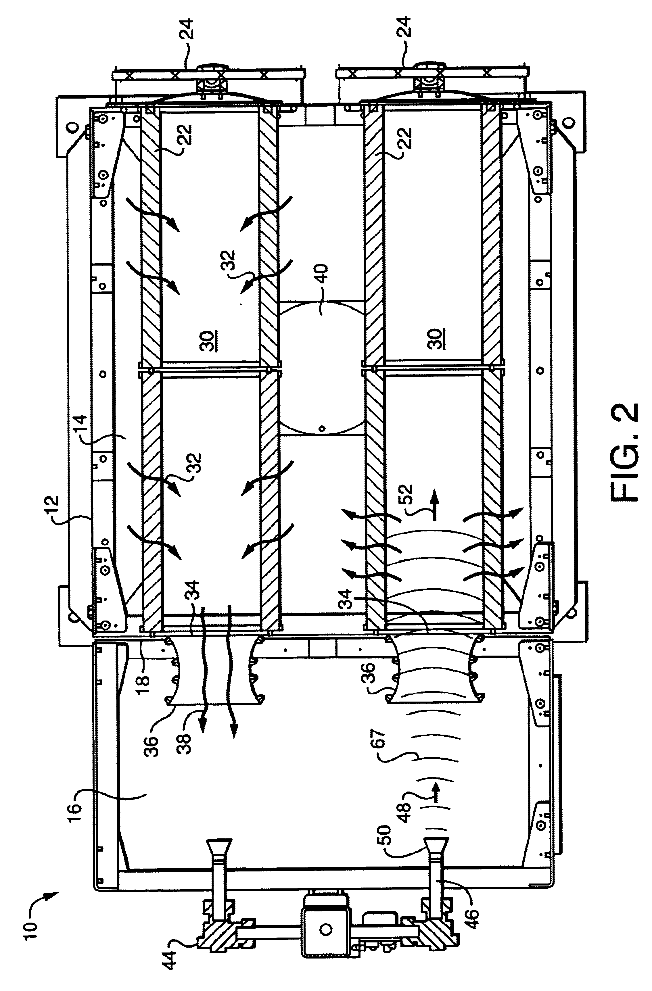
[0020]Referring now to FIG. 2, it can be seen that the illustrated filtration unit includes four substantially tubular filter media units 22. In the illustrated embodiment, these filtration units 22 are tubular pleated paper cartridges that are axially inserted through a door unit 24. The cartridges are supported by exterior rails 26 and the upper unit 22 is protected from excessive top build...


PUM

PropertyMeasurementUnit
Timeaaaaaaaaaa
Pressureaaaaaaaaaa
Pressureaaaaaaaaaa

Abstract

Shown is an apparatus and method for cleaning filter units of an air filtering system using a reverse flow pulse of pressurized air. The filter cleaning system includes a venturi element (36) with a narrowed throat portion (56). A blowpipe (46) is substantially axially aligned with the venturi (36) and has an outlet nozzle (50) that is flared in a substantially conical shape with an included angle that (64) that exceeds an angle at (62) at which high pressure air would ordinarily diverge from an unmodified blowpipe opening. The nozzle (50) is axially spaced from the venturi at a selected distance (70) such that a high velocity pulse of air delivered by the blowpipe (46) through the nozzle (50) is delivered to the outlet portion (58) of the venturi (36) substantially between the outlet opening (62) and the throat (56). This relationship provides a cleaning pulse of air that effectively completely chokes all forward movement of air flow through the venturi (36) and delivers a pulse wave of high pressure, high velocity air along substantially the full length of the tubular filter element (22).

Description

TECHNICAL FIELD[0001]This invention relates to a method and device for cleaning filter units of an air filtering system using reverse flow pulsed jets of pressurized air.BACKGROUND OF THE INVENTION[0002]Many industries encounter a problem with particulate matter suspended in a gas, such as air. In some situations, the particulate matter is a valuable product to be recovered. In other situations, the particulate matter is simply a pollutant to be removed prior to discharge or recirculation.[0003]Systems for cleaning an air or gas stream laden with particular matter include air filter assemblies that have filter elements situated in a housing. The filter element may be a bag made of suitable fabric or a rigid media such as pleated paper. Cleaning of the filter element(s) may be accomplished by periodically pulsing a brief jet of pressurized air in a reverse flow through the filter element. Such air filter assemblies are disclosed in, for example, U.S. Pat. No. 6,090,173 (Johnson, et a...

Claims


Application Information

Patent Timeline
07 Jun 2005
Publication
US6902592B2
IPC
B01D46/04; B01D46/00; B01D46/24; B01D46/52
CPC
B01D46/0068; B01D46/521; B01D46/4281; B01D46/2411; B01D46/71
Inventors
GREEN, THOMAS B.; SWAIN, CHRISTOPHER S.