System for stabilizing the vertebral column including deployment instruments and variable expansion inserts therefore

a technology of vertebral column and deployment instrument, which is applied in the field of medical devices, can solve the problems of traumatic lesions to adjacent anatomic structures, delayed deployment and mounting of bolt-based fixation devices, and difficult use, and achieves the effects of simple construction, simple use, and simple construction

Inactive Publication Date: 2005-06-14
PHOENIX BIOMEDICAL
View PDF26 Cites 302 Cited by
  • Summary
  • Abstract
  • Description
  • Claims
  • Application Information

AI Technical Summary

Benefits of technology

[0010]It is another object of this invention to provide a device and system for deploying it in the intervertebral space between a superior and inferior vertebra of a living being to stabilize the spine.
[0024]The expansion insert has an externally threaded outer surface and is arranged to be screwed into the internally threaded bore in the proximal end portion of the expandable insert when the expandable insert is in the desired position and orientation. In a preferred embodiment the outer surface of the expansion insert is tapered from the proximal end to the distal end. Thus, when the expansion insert is screwed into the threaded bore in the expandable insert, it causes the slots to open and thereby spread the superior and inferior vertebrae apart, thereby stabilizing the being's vertebral column.

Problems solved by technology

One of the greatest drawbacks of such prior art devices or systems are that they are difficult to use.
In this regard, the deployment and mounting of a bolt-based fixation device is delayed by the necessity to bore the bony structures of the vertebrae for receipt of the securement bolts.
Another drawback of such spine fixation devices is the fact that they typically take up such substantial space in the body when secured in place, that they may result in the formation of traumatic lesions to adjacent anatomic structures.
Lastly, traction exerted by movement of the patient, may cause partial or total detachment of one or more of the bone fixation bolts, which action may also result in the formation of traumatic lesions to adjacent anatomic structures and / or instability of part or all of the fixation system.
While the spine stabilization or fixation devices of the patent literature may be generally suitable for their intended purposes, they still leave much to be desired from the standpoints of ease of use and effectiveness.
For example, some prior art spine fixation devices require excision of the anterior and / or posterior ligaments, thereby destabilizing the spine.
This type of fixation device may be prone to damage the immediately adjacent vertebrae due to compressive forces thereon.
While some prior art devices don't require excision of the ligaments to effect spine stabilization, they, nevertheless, typically require the partial or complete extraction and removal of the disk in order to place them into the intervertebral space, where such devices seek to replace the function of the disk (albeit less than optimally).

Method used


Image

  • System for stabilizing the vertebral column including deployment instruments and variable expansion inserts therefore
  • System for stabilizing the vertebral column including deployment instruments and variable expansion inserts therefore
  • System for stabilizing the vertebral column including deployment instruments and variable expansion inserts therefore

Examples


Embodiment Construction

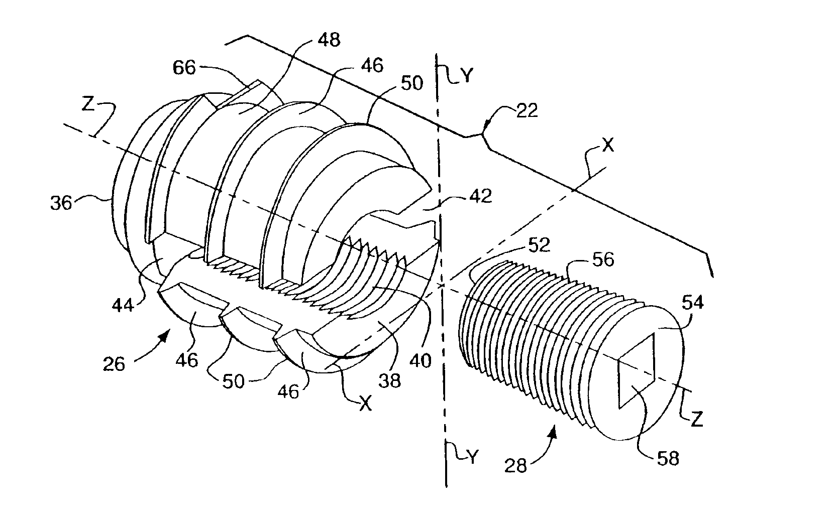
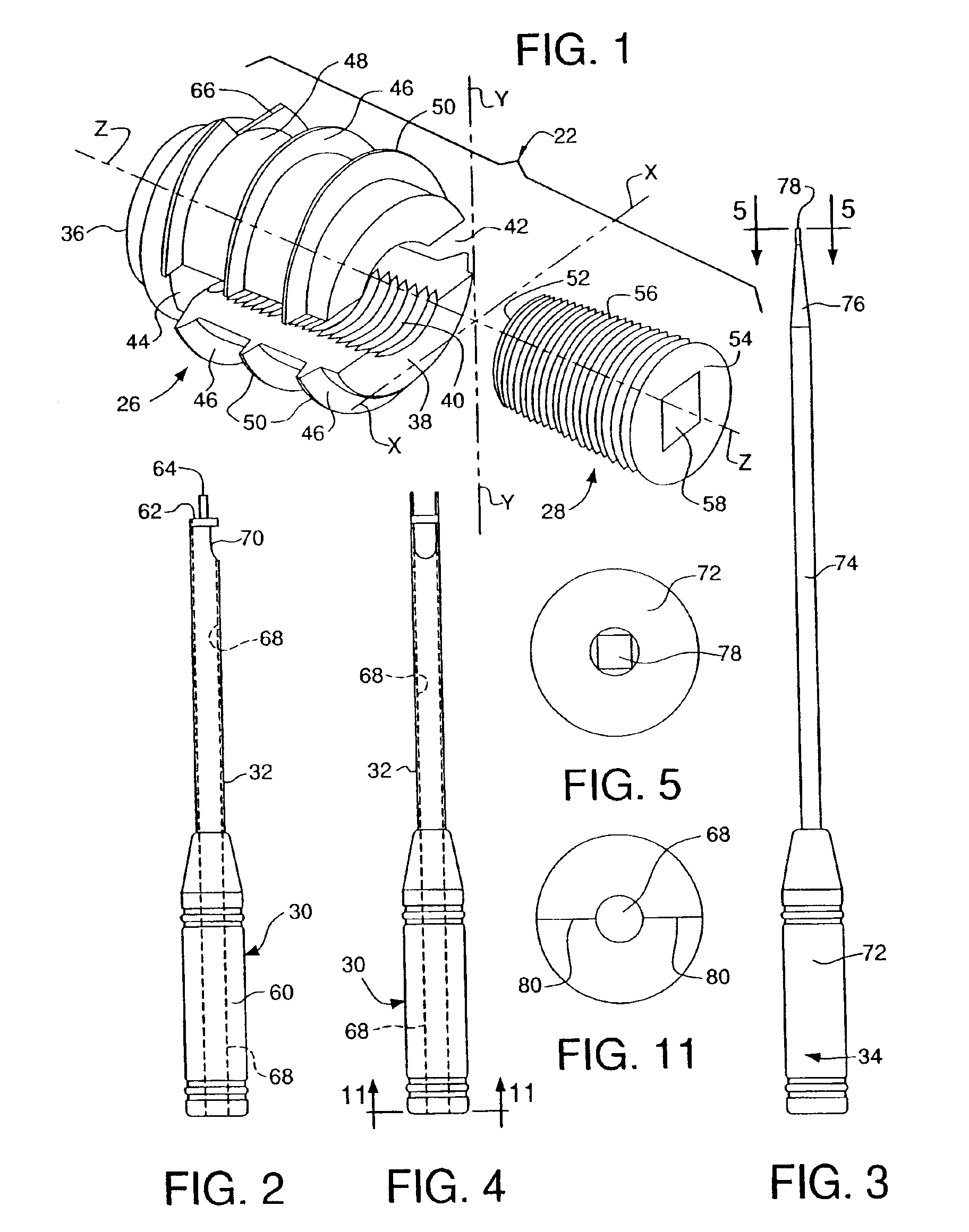
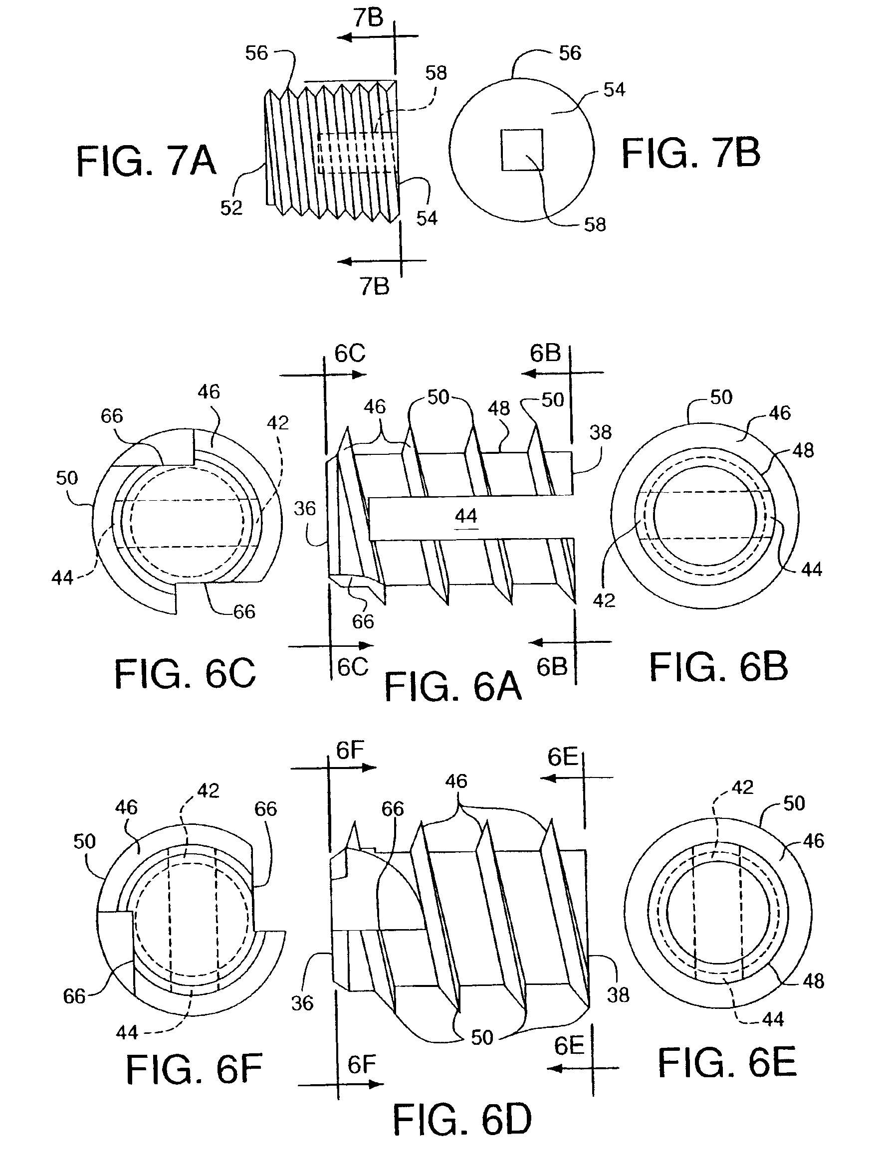
[0045]Referring now to the various figures of the drawing wherein like reference characters refer to like parts, there is shown generally at 20 in FIG. 9 a system for stabilizing the spinal column 10 of a living being. The system 20 basically comprises a stabilization device 22 and a deployment system 24 for the device. The stabilization device 22 is itself composed of two components, namely, a self-tapping expandable insert 26 and an expansion insert or screw 28 (see FIG. 1). The details of the insert 26 and expansion screw 28 will be described later. Suffice for now to say that the insert 26 is arranged to be screwed into the intervertebral space 12 between a superior vertebrae 14A and an inferior vertebrae 14B at the location to be stabilized as selected by the surgeon. Insert 26 is screwed into place by a first one of two tools making up the deployment system 24.

[0046]Once the insert 26 is in place, the expansion screw 28 is screwed into the insert 26 by the second tool of the d...


PUM


Abstract

A system is provided for stabilizing adjacent vertebra without excision of bone or resection of ligaments comprising an expansion device and a deployment system which includes a hollow expandable insert and an expansion insert. The expandable insert includes a cylindrical body having a pair of slots having a threaded outer surface. The expandable insert is located with the slots oriented perpendicular to the vertebral column between the vertebrae. The thread cuts into the cortical bone contiguous to the intervertebral space but not substantially into the cancellous bone. The expandable insert is internally threaded. The expansion insert is externally threaded and arranged to be screwed into a bore in the expandable insert by the deployment system, whereupon the slots open to spread the vertebrae apart. The deployment system includes a tool having projecting fingers located within the slots to enable the expandable insert to be screwed into the intervertebral space.

Description

CROSS-REFERENCE TO RELATED APPLICATION[0001]This is a Divisional application of application Ser. No. 09 / 348,612, filed on Jul. 6, 1999, now U.S. Pat. No. 6,436,142 entitled System for Stabilizing the Vertebral Column Including Deployment Instruments and Variable Expansion Inserts Therefor.FIELD OF THE INVENTION[0002]This invention relates generally to medical devices and more specifically to intervertebral disk stabilization systems and methods of stabilizing the spine of living beings.BACKGROUND OF THE INVENTION[0003]This application claims priority on Brazilian Patent Application, Serial Number 9805340-0, filed on Dec. 14, 1998, entitled VARIABLE EXPANSION INSERT FOR STABILIZING THE VERTEBRAL COLUMN, whose disclosure is incorporated by reference herein.[0004]Numerous types of devices or systems are available for the fixation of the vertebral column of living beings. For example, some devices are prostheses, e.g., plates or other structures, formed of rigid materials of fixed sizes...

Claims


Application Information

Patent Timeline
Patent Type & Authority Patents(United States)
IPC IPC(8): A61F2/44A61F2/46A61B17/88A61F2/00A61F2/30A61F2/02A61B1/00
CPCA61B17/8615A61F2/442A61F2/446A61F2/4611A61F2/4637Y10S623/908A61F2002/30154A61F2002/30235A61F2002/30405A61F2002/30408A61F2002/30507A61F2002/30538A61F2002/30579A61F2002/30594A61F2002/30604A61F2002/30616A61F2002/30617A61F2002/30706A61F2002/30772A61F2002/30795A61F2002/30797A61F2002/30858A61F2002/30863A61F2002/4475A61F2002/4623A61F2002/4635A61F2002/4638A61F2220/0025A61F2230/0021A61F2230/0069A61F2250/0006A61F2250/0082A61F2250/0097A61F2310/00023A61B17/888A61F2/4603A61F2002/30593
Inventor PAES, NEWTONPAES, VERA
Owner PHOENIX BIOMEDICAL
Why Eureka
Try Eureka