Glass antenna and glass antenna system using the same

a technology of glass antenna and glass antenna, which is applied in the direction of antennas, antenna details, antenna adaptation in movable bodies, etc., can solve the problems of difficult to achieve a consistently superior receiving sensitivity, deterioration of the reception sensitivity of the antenna provided at the lower margin portion, and adverse influence of the rear tray of the car body

Inactive Publication Date: 2005-06-14
NIPPON SHEET GLASS CO LTD
View PDF15 Cites 10 Cited by
  • Summary
  • Abstract
  • Description
  • Claims
  • Application Information

AI Technical Summary

Benefits of technology

[0014]It is an object of the present invention to provide a glass antenna for vehicles whose receiving sensitivity does not decrease c

Problems solved by technology

More specifically, the receiving sensitivity of the antenna provided at the lower margin portion often deteriorates.
Furthermore, it is also susceptible to the adverse influence of the rear tray of the

Method used


Image

  • Glass antenna and glass antenna system using the same
  • Glass antenna and glass antenna system using the same
  • Glass antenna and glass antenna system using the same

Examples


example 1

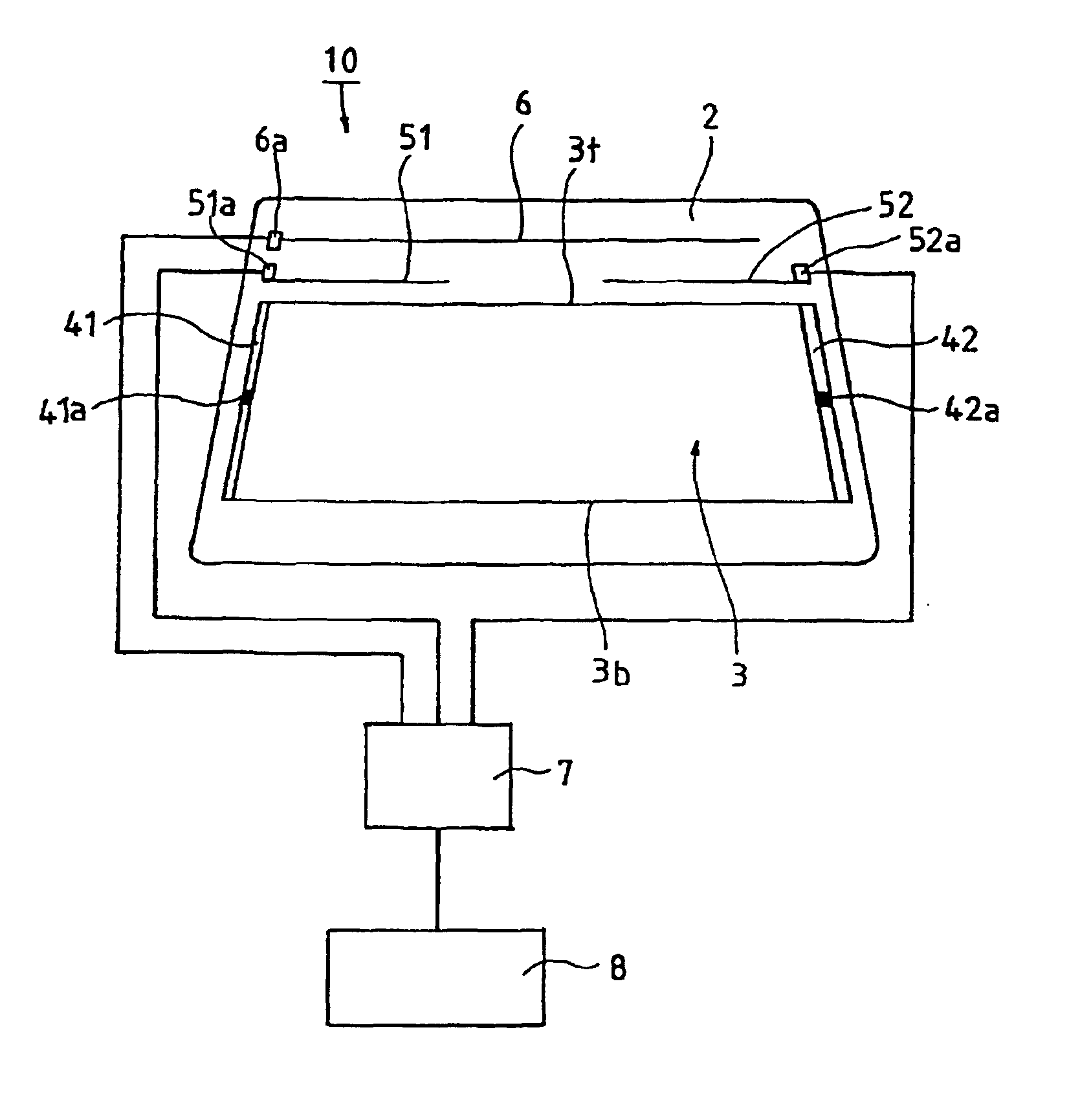
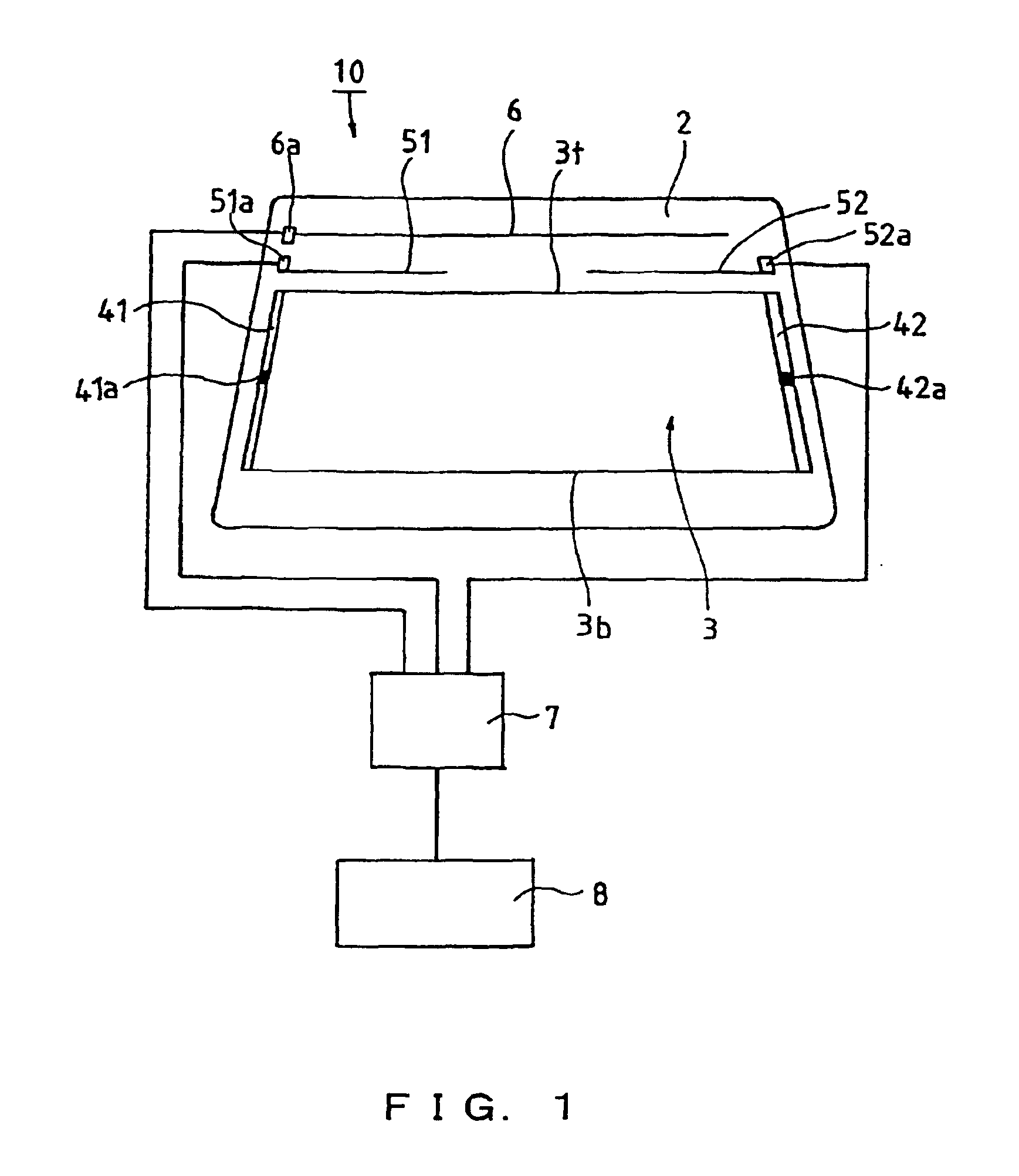
[0041]In a glass antenna system 10 as shown in FIG. 1, a defogging heater 3 is provided in the middle of a vehicle rear window glass 2. The respective ends of the heater lines that constitute the defogging heater 3 are connected to bus bars 41 and 42. In some of the attached drawings, heater lines other than the top line 3t and the bottom line 3b are not shown. Feeding points 41a and 42a provided on the bus bars are connected via a switch mechanism (not shown in the drawings) to a power source (not shown in the drawings).

[0042]The heater lines, the bus bars, and the antenna elements described below can be made by applying silver paste in a predetermined pattern.

[0043]A first antenna element 51 is formed as a bar-shaped horizontal line extending from a first antenna feeding point 51a provided on the left side of the glass at a margin portion above the heater line 3t. The first antenna element 51 is connected via a terminal provided at the feeding point 51a to a diversity module 7. A ...

specific example 1

[0069]In the glass antenna 1 shown in FIG. 11, a defogging heater 3 is provided in the middle of a vehicle rear window glass 2. The respective ends of the heater lines 3t to 3b constituting the defogging heater 3 are connected to bus bars 41 and 42.

[0070]A first antenna element 51 is formed as a bar-shaped horizontal conductor element extending from a feeding point 51a for the first antenna element provided on the left side of the glass at a margin portion above the heater line 3t of the defogging heater 3.

[0071]A second antenna element 52 includes a loop-shaped pattern extending from a feeding point 52a for the second antenna element provided on the right side of the glass at a margin portion above the heater line 3t of the defogging heater 3.

[0072]The defogging heater 3 is provided with a shorting line 31 for shorting the middle portions of some of the heater lines, including the top line 3t.

specific example 2

[0073]Specific Example 2 is a glass antenna 1, in which the first antenna element of Specific Example 1 has been modified. As shown in FIG. 12, the first antenna element 51 has a two-tine fork pattern, whereas the second antenna element 52 has a loop-shaped pattern.

[0074]Also in this Specific Example 2, the defogging heater 3 is provided with a shorting line 31.

[0075]Moreover, the pattern of the medium wave antenna 6 is a little different from that in Specific Example 1.


PUM


Abstract

A glass antenna of the present invention includes a window glass: a defogging heater including a plurality of conductive lines arranged on the window glass; a first antenna element and a second antenna element arranged at an upper side relative to the heater on the window glass; and a first feeding point for the first antenna element arranged at a left side of the window glass, and a second feeding point for the second antenna element arranged at a right side of the window glass. The first antenna element and the second antenna element each are capacitively coupled with the heater.

Description

FIELD OF THE INVENTION[0001]The present invention relates to a glass antenna for vehicles, and in particular to a glass antenna system including a diversity antenna that is suitable for receiving signals in the very high frequency (VHF) bandBACKGROUND OF THE INVENTION[0002]Glass antennas in which conductive lines are formed on a vehicle window glass are superior to conventional rod antennas in that (i) they are designed not to protrude outward, (ii) there is little danger of breakage, and (iii) they do not cause wind noise. For these and other reasons, such glass antennas are in widespread use.[0003]When receiving radio waves in the VHF band (FM band and TV band), the antenna element often receives reflecting waves as well as direct waves from the broadcasting antenna. The reflecting waves are reflected from the ground and from structures such as buildings. Sometimes, not only one reflecting wave but also several reflecting waves reach the antenna element from several reflection pat...

Claims


Application Information

Patent Timeline
IPC IPC(8): H01Q1/12H01Q1/32
CPCH01Q1/1278
Inventor OKA, HIDETOSHI
Owner NIPPON SHEET GLASS CO LTD
Why Eureka
Try Eureka