FSS feeding network for a multi-band compact horn

a multi-band, compact horn technology, applied in the direction of horns, slot antennas, waveguide horns, etc., can solve the problems of multiple feed probes, limited operation frequency and bandwidth of conventional horns,

Inactive Publication Date: 2005-06-14
NORTH SOUTH HLDG
View PDF7 Cites 229 Cited by
  • Summary
  • Abstract
  • Description
  • Claims
  • Application Information

AI Technical Summary

Problems solved by technology

Since horns are generally designed to have a static geometry, the operational frequency and bandwidth of conventional horns are limited.
However, the coaxial nature of the feed structures in the multi-band horn antenna proposed by Loughborough prevents multiple feed probes from being incorporated into the multi-band horn antenna in a conventional fashion.

Method used


Image

  • FSS feeding network for a multi-band compact horn
  • FSS feeding network for a multi-band compact horn
  • FSS feeding network for a multi-band compact horn

Examples


Embodiment Construction

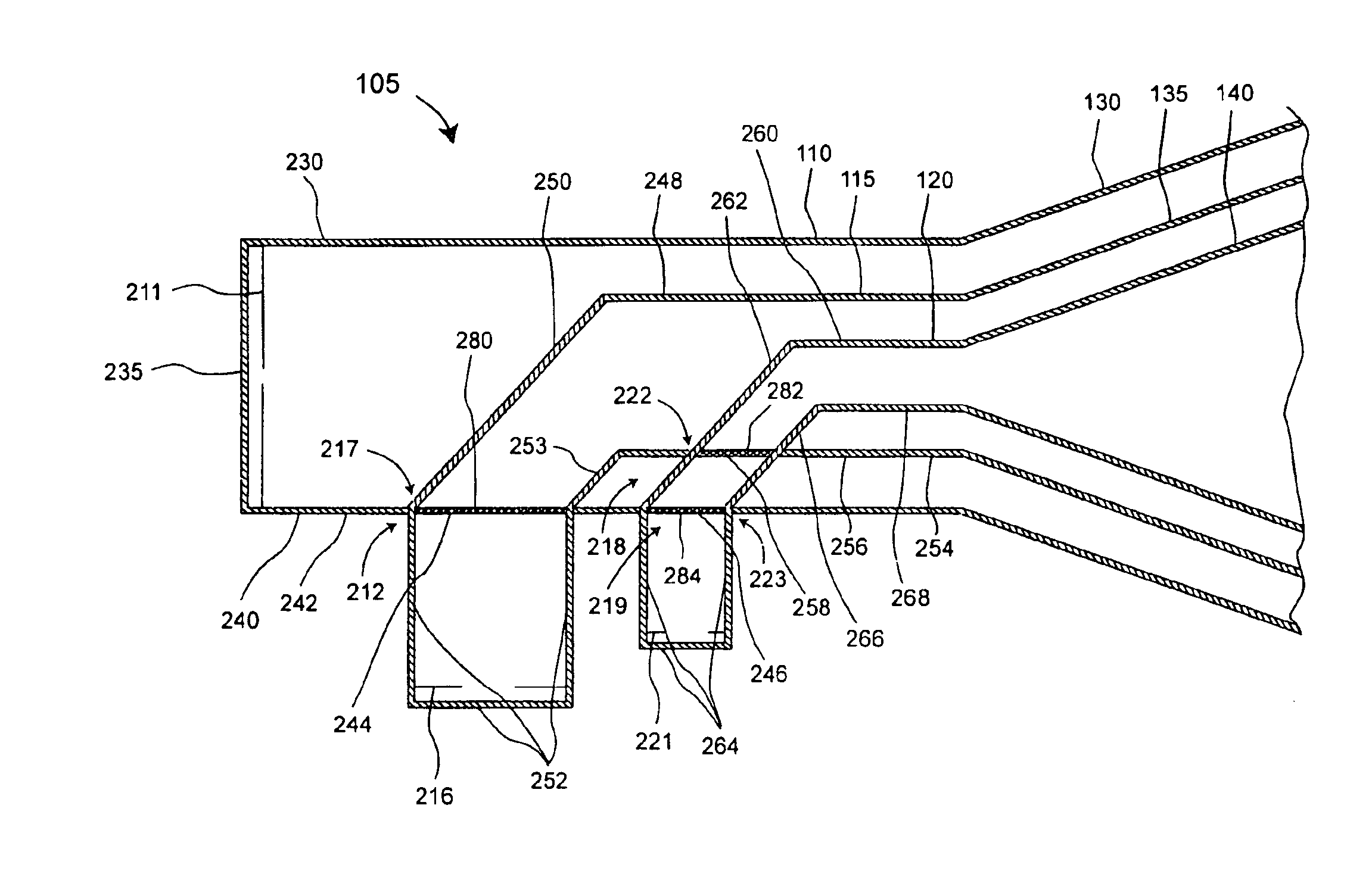
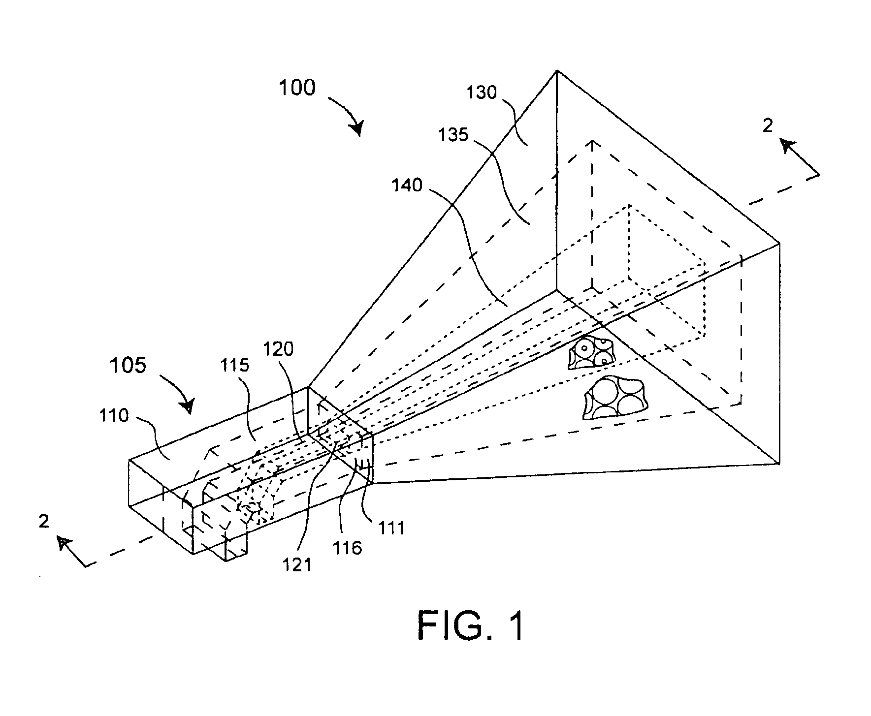
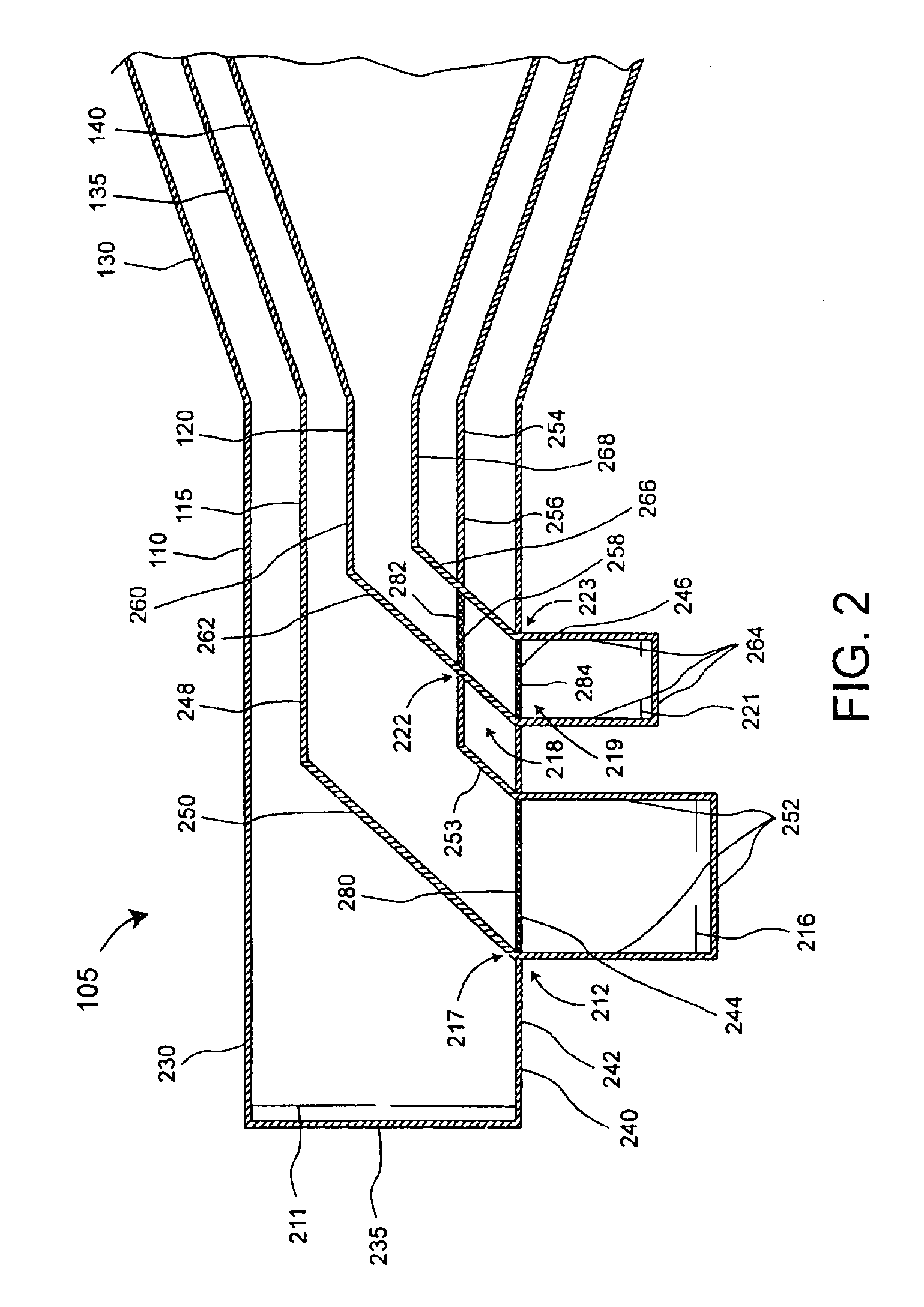
[0019]An embodiment of the present invention concerns a feed structure for use with a multi-band horn antenna. The feed structure includes a waveguide combiner network which can include a plurality of waveguides that are operatively coupled to antenna horns. For example, a waveguide can be provided for each of a plurality of coaxial horns. Further, a feed probe can be provided for each of the waveguides. Accordingly, the feed probes can be optimized for the horns with which they are used.

[0020]Frequency selective surfaces (FSS's), which are known in the art, can be selectively incorporated into walls of the waveguides such that the waveguides are reflective at selected frequencies and transparent at other selected frequencies. For instance, a particular waveguide can be reflective for RF signals generated by a feed probe associated with the waveguide, yet be transparent to RF signals generated by feed probes associated with other waveguides within the feed structure. Accordingly, th...


PUM


Abstract

A feed structure (105) for a horn antenna (100). The feed structure can include a first waveguide (110) and a second waveguide (115) having a first portion at least partially disposed within the first waveguide. The second waveguide also can include a second portion intersecting a first wall (240) of the first waveguide. The first wall can include a first frequency selective surface (244) at an intersection (280) of the first wall and the second portion of the second waveguide. The first waveguide can be operatively coupled to a first horn section (130) and the second portion can be operatively coupled to a second horn section (135).

Description

BACKGROUND OF THE INVENTION[0001]1. Statement of the Technical Field[0002]The inventive arrangements relate generally to methods and apparatus for horn antennas, and more particularly to horn antennas which can operate in multiple frequency bands.[0003]2. Description of the Related Art[0004]Conventional electromagnetic waveguides and horn antennas are well known in the art. A waveguide is a transmission line structure that is commonly used for microwave signal transmission. A horn antenna (horn) is a particular type of waveguide which is optimized for wireless propagation and reception of RF signals through free space. Horns typically have a conical or pyramidal shape. In a common configuration, a narrow end of the horn is operatively connected to one end of a feed structure, which itself includes a waveguide. A feed probe is usually installed at an end of the feed structure which is opposite of the end of the feed structure that is joined with the horn. The feed probe couples the h...

Claims


Application Information

Patent Timeline
Patent Type & Authority Patents(United States)
IPC IPC(8): H01Q13/00H01Q5/00H01Q5/47H01Q13/02H01Q15/00
CPCH01Q13/02H01Q5/47H01Q15/0013
Inventor KILLEN, WILLIAM D.DELGADO, HERIBERTO J.ZARRO, MICHAEL S.
Owner NORTH SOUTH HLDG
Why Eureka
Try Eureka