Method and apparatus actively damping mechanical vibration and shock in head suspensions of a disk drive

a disk drive and suspension technology, applied in the direction of maintaining the head carrier alignment, recording information storage, instruments, etc., can solve the problems of severe mechanical vibration of the suspension, adversely affecting the actuator as a whole, and the shock of the drive's head suspension

a disk drive and suspension technology, applied in the direction of maintaining the head carrier alignment, recording information storage, instruments, etc., can solve the problems of severe mechanical vibration of the suspension, adversely affecting the actuator as a whole, and the shock of the drive's head suspension

US6909571B2Inactive Publication Date: 2005-06-21SAMSUNG ELECTRONICS CO LTD

Image

  • Method and apparatus actively damping mechanical vibration and shock in head suspensions of a disk drive
  • Method and apparatus actively damping mechanical vibration and shock in head suspensions of a disk drive
  • Method and apparatus actively damping mechanical vibration and shock in head suspensions of a disk drive

Examples


Embodiment Construction

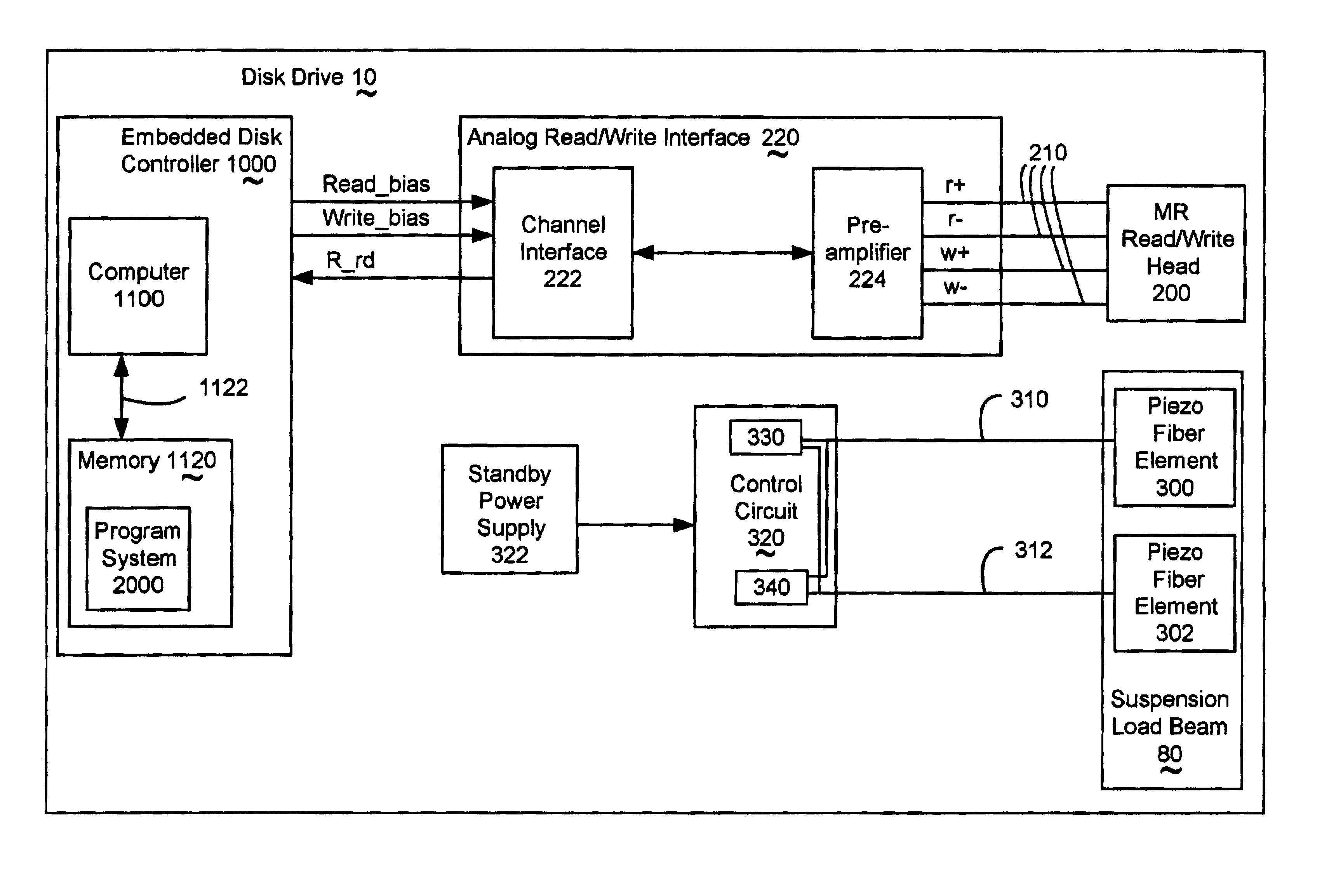
[0045]The invention includes a method of attenuating resonance frequency modes in head suspensions, which does not significantly increase the weight of the head suspension. The invention provides a way to control the head deflection from the disk surface, which helps minimize damage from head slapping. The invention includes a basic head suspension infrastructure for which vibration resonance can be predictably controlled.

[0046]FIG. 3 illustrates a head suspension 60, including a load suspension beam 80, with two integrated piezo fiber elements 300 and 302, providing signals to conductors 310 and 312 to a means 320, which are collectively included in disk drive 10.

[0047]The load suspension beam 80 operates as follows. At least two differential signals are provided from the suspension load beam 80 indicating mechanical bending of the suspension load beam 80. Whenever the differential signals indicate mechanical bending an out-of-phase electrical signal is sent back to the suspension ...


PUM

PropertyMeasurementUnit
mechanical bendingaaaaaaaaaa
bending thresholdaaaaaaaaaa
bending rateaaaaaaaaaa

Abstract

The invention includes a method of attenuating resonance frequency modes in head suspensions, which does not significantly increase the weight of the head suspension. The invention provides a way to control the head deflection from the disk surface, which helps minimize damage from head slapping. The invention includes a basic head suspension infrastructure for which vibration resonance can be predictably controlled.

Description

TECHNICAL FIELD[0001]This invention relates to reducing mechanical vibration and shock in the head suspensions of a disk drive to improve reliability.BACKGROUND ART[0002]Disk drives are an important data storage technology. Read-write heads are one of the crucial components of a disk drive, directly communicating with a disk surface containing the data storage medium. The invention relates to actively compensating for mechanical strains on the infrastructure holding the read-write head close to the disk surface.[0003]FIG. 1A illustrates a typical prior art high capacity disk drive 10 including actuator 30 with voice coil 32, actuator axis 40, actuator arms 50-58 with head gimbal assembly 60 placed among the disks.[0004]FIG. 1B illustrates a typical prior art high capacity disk drive 10 with head stack assembly 20 including actuator 30 with voice coil 32, actuator axis 40, actuator arms 50-56 and head gimbal assemblies 60-66 with the disks removed.[0005]FIG. 2A illustrates a head gim...

Claims


Application Information

Patent Timeline
21 Jun 2005
Publication
US6909571B2
IPC
G11B5/58; G11B5/48; G11B21/02
CPC
G11B5/58; G11B5/4853; G11B21/02
Inventors
BOLJANOVIC, MOMO