Collapsible concrete forms

a concrete form and collapsible technology, applied in the field of concrete forms, can solve the problem of not allowing further pivoting, and achieve the effect of facilitating storage and minimal loss of storage volum

Inactive Publication Date: 2005-07-12
TIBERION BLOCK LLC
View PDF29 Cites 65 Cited by
  • Summary
  • Abstract
  • Description
  • Claims
  • Application Information

AI Technical Summary

Benefits of technology

[0008]Referring to FIG. 1 so that the following arrangement is more readily envisioned, a concrete form unit includes opposing sidewalls which are preferably made of foamed plastic or other insulating material. Webs are embedded within the sidewalls, with protruding web portions extending out of the sidewalls into a space located between the sidewalls. Spacers extending between and connecting the sidewalls each include a pair of rigid spacer links, each spacer link including a wall end pivotally linked to a sidewall at a protruding web portion, and an elbow end pivotally linked to the other of the spacer links within the spacer. The pivotable connections of the spacer links allow the sidewalls to convert between a collapsed state wherein the sidewalls are in close adjacent relationship and the spacer links are oriented at least substantially parallel to each other and at least substantially parallel to the sidewalls (FIG. 4), and an expanded state wherein the sidewalls are in distant spaced relationship with the spacer links being oriented at least substantially parallel to each other and at least substantially perpendicular to the sidewalls (FIGS. 1 and 2). Each concrete form unit has sidewalls configured with opposing top and bottom ends, and also opposing side ends, wherein the top ends are configured to abut the bottom ends of the sidewalls of another concrete form unit in interlocking relationship. As a result of the foregoing arrangement, concrete form units may be shipped in their collapsed state, converted to their expanded state at a construction side, and stacked in interlocking form to construct a larger concrete form for the casting of large walls and other structures. The use of spacers having dual pivoting spacer links allows a form unit to collapse with the adjacent side ends of the sidewalls being situated in coplanar relationship (FIG. 4), with the collapsed form unit assuming an overall box-like shape, and therefore the collapsed form units are easily stored and shipped with minimal lost storage volume.
[0009]The concrete form units preferably include some form of stabilizing means for assisting in maintaining the form units in their expanded states without buckling. Such stabilizing means may take the form of stops situated on the elbow ends of the spacer links which allow the spacer links to pivot from the collapsed position, but which interfere with each other once the spacer links achieve the expanded state, and do not allow further pivoting thereafter (save for pivoting back to the collapsed state). If desired, the stops may further bear latching structures which then resist pivoting back to the collapsed state. The stabilizing means may additionally or alternatively take the form of latching structures on the spacer link wall ends and / or on the protruding web portions to which the spacer link wall ends are pivotally connected, so that the spacer links may rotate with respect to the sidewalls to the expanded state, but resist further pivoting out of the expanded state. This can be done, for example, by providing the spacer link wall ends with corners which interfere with the sidewalls about which they pivot, the corners being oriented such that the spacer links initially resist pivoting into the expanded state owing to interference between the corners and the sidewalls (or their protruding web portions). However, once the spacer links are urged into the expanded state, this interference will also resist the pivoting of the spacer links out of the expanded state, and thus the spacer links will be resiliently “clicked” into the expanded state. By use of the stabilizing means, a user may set concrete form units in their expanded states, and use them to assemble a larger concrete form, without the inconvenience of having form units which are prone to buckling towards their collapsed states when working with them.

Problems solved by technology

Such stabilizing means may take the form of stops situated on the elbow ends of the spacer links which allow the spacer links to pivot from the collapsed position, but which interfere with each other once the spacer links achieve the expanded state, and do not allow further pivoting thereafter (save for pivoting back to the collapsed state).

Method used


Image

  • Collapsible concrete forms
  • Collapsible concrete forms
  • Collapsible concrete forms

Examples


Embodiment Construction

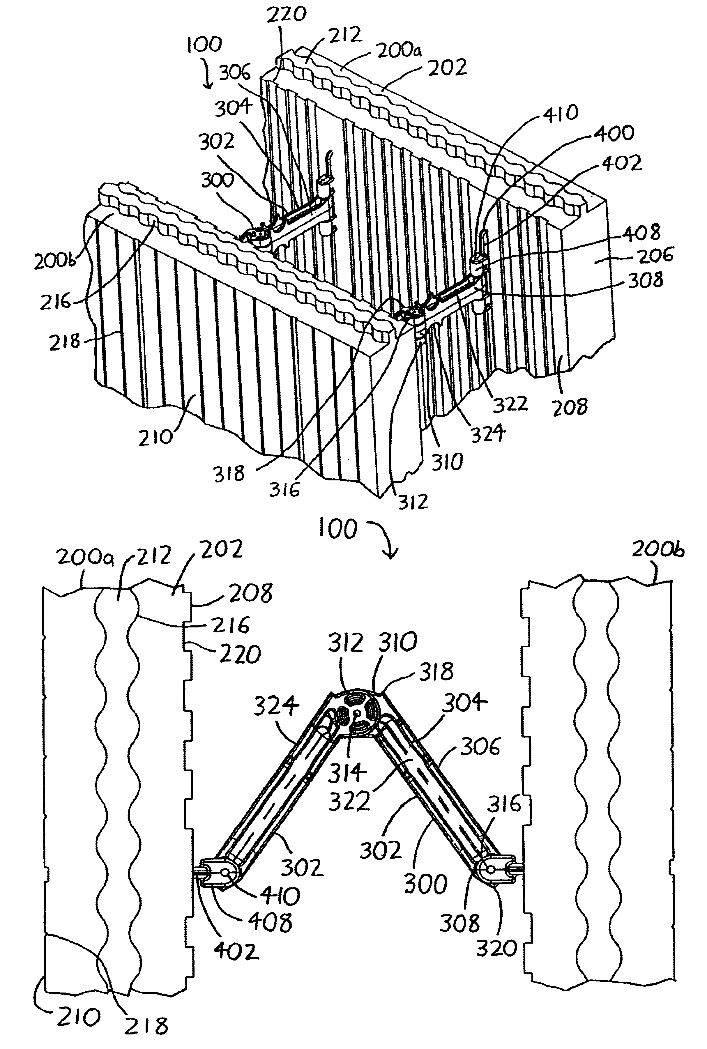
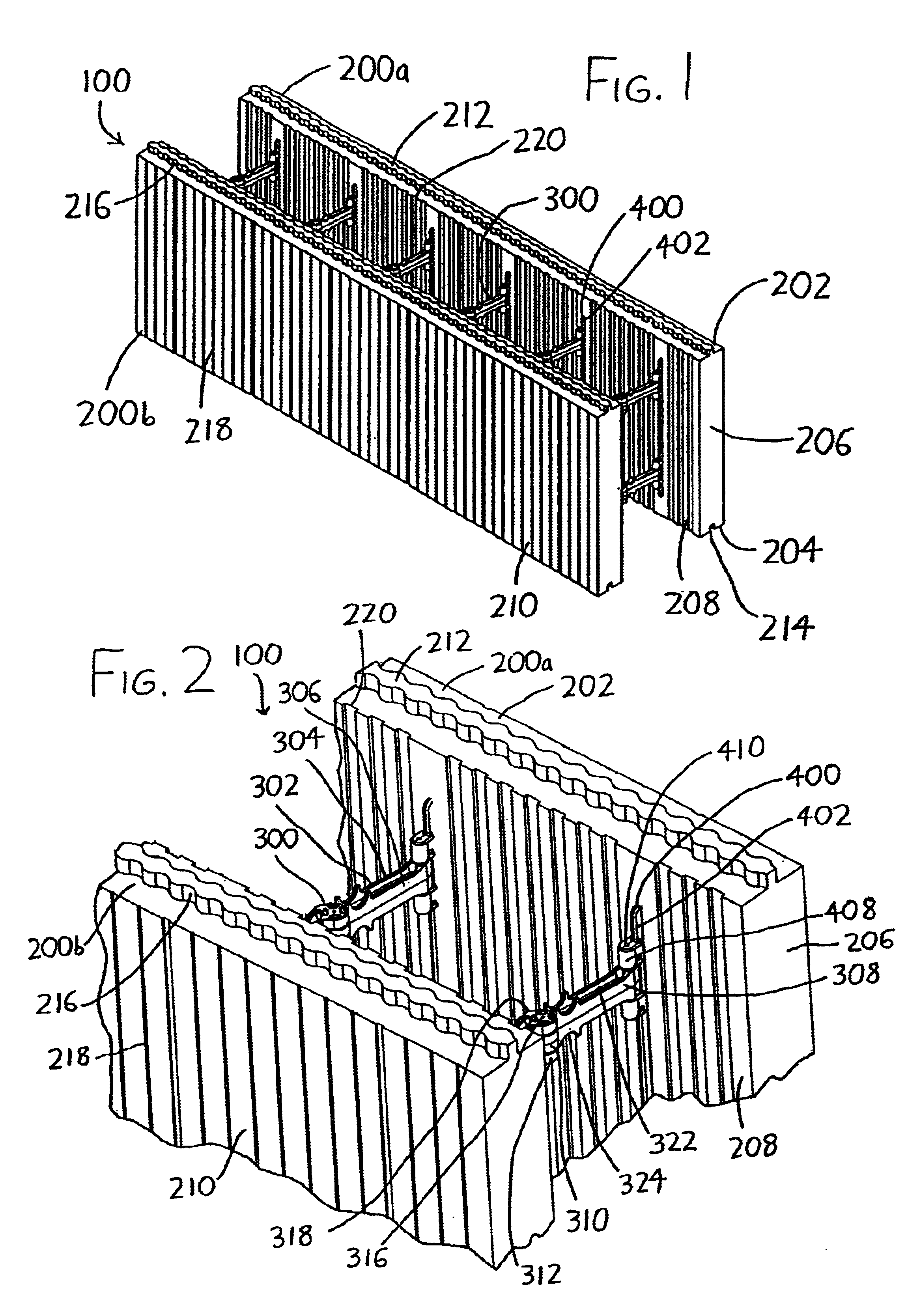
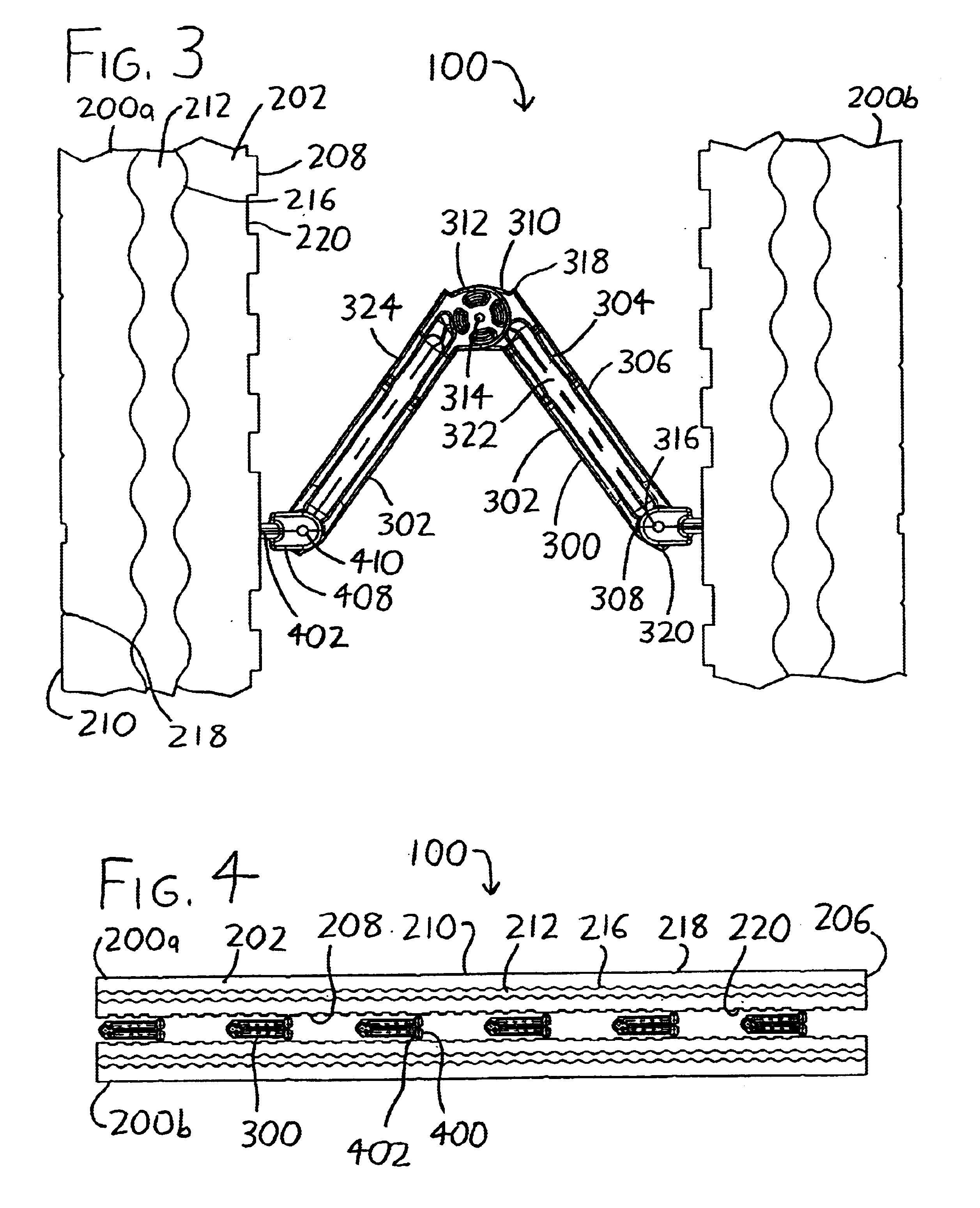
[0017]Referring particularly to FIGS. 1-4, an exemplary preferred version of a collapsible concrete form unit is depicted generally by the reference numeral 100. The concrete form unit 100 includes sidewalls 200a and 200b (hereinafter collectively referred to as sidewalls 200) between which concrete is to be poured when the concrete form unit 100 is used within a concrete form (i.e., when multiple concrete form units 100 are assembled into a completed concrete form). The concrete form unit 100 additionally includes spacers 300, which serve to hold the sidewalls 200 in spaced relation during the pouring and setting of concrete therebetween. As will be discussed in greater detail below, the concrete form unit 100 is collapsible from the expanded state (illustrated in FIGS. 1 and 2) to a collapsed state (illustrated in FIG. 4), with the spacers 300 being articulated to hingedly fold between the expanded and collapsed states. This transition can be partially envisioned with reference to...


PUM


Abstract

A concrete form unit includes opposing sidewalls which are preferably made of foamed plastic or other insulating material. Articulated spacers extend between and connect the sidewalls, and are capable of folding about themselves both at an elbow situated between the sidewalls, and also at their junctures with the sidewalls. The folding ability of the spacers allow the sidewalls to convert between a collapsed state wherein the sidewalls are in close adjacent relationship and the spacer links are oriented at least substantially parallel to each other and at least substantially parallel to the sidewalls, and an expanded state wherein the sidewalls are in distant spaced relationship with the spacer links being oriented at least substantially parallel to each other and at least substantially perpendicular to the sidewalls. The collapsed form unit therefore assumes an overall box-like shape, and therefore the collapsed form units are easily stored and shipped with minimal lost storage volume.

Description

CROSS-REFERENCE TO RELATED APPLICATIONS[0001]This application claims priority under 35 USC §119(e) to U.S. Provisional Patent Application 60 / 430,176 filed 2 Dec. 2002, the entirety of which is incorporated by reference herein.FIELD OF THE INVENTION[0002]This document concerns an invention relating generally to concrete forms for casting poured concrete, and more specifically to insulated concrete forms (commonly referred to as “ICFs”) wherein the forms include inner and outer insulated sidewalls which receive poured concrete therebetween.BACKGROUND OF THE INVENTION[0003]The construction industry has experienced a growing trend in the use of insulated concrete forms (ICFs), wherein forms for pouring concrete are constructed from multiple modular form units. Each unit includes inner and outer sidewalls, at least one of which is formed of foamed polystyrene, foamed polyurethane, or other cellular plastics or insulating materials. The sidewalls of the form units are stacked or otherwise...

Claims


Application Information

Patent Timeline
Patent Type & Authority Patents(United States)
IPC IPC(8): E04B2/86
CPCE04B2/8617E04B2/8635E04B2002/8694
Inventor WOSTAL, TERRY K.PASKE, STEVEN J.
Owner TIBERION BLOCK LLC
Why Eureka
Try Eureka