
Mine detonating apparatus and vehicle including such apparatus

a technology of detonating equipment and vehicles, which is applied in the direction of marine mines, waterborne vessels, defence devices, etc., can solve the problems of affecting the mobility of vehicles, too heavy to carry on armoured personnel carriers, and only weighing approximately 10 to 20 tonn

Inactive Publication Date: 2005-07-12
PEARSON ENG
View PDF6 Cites 27 Cited by
  • Summary
  • Abstract
  • Description
  • Claims
  • Application Information

AI Technical Summary

Benefits of technology

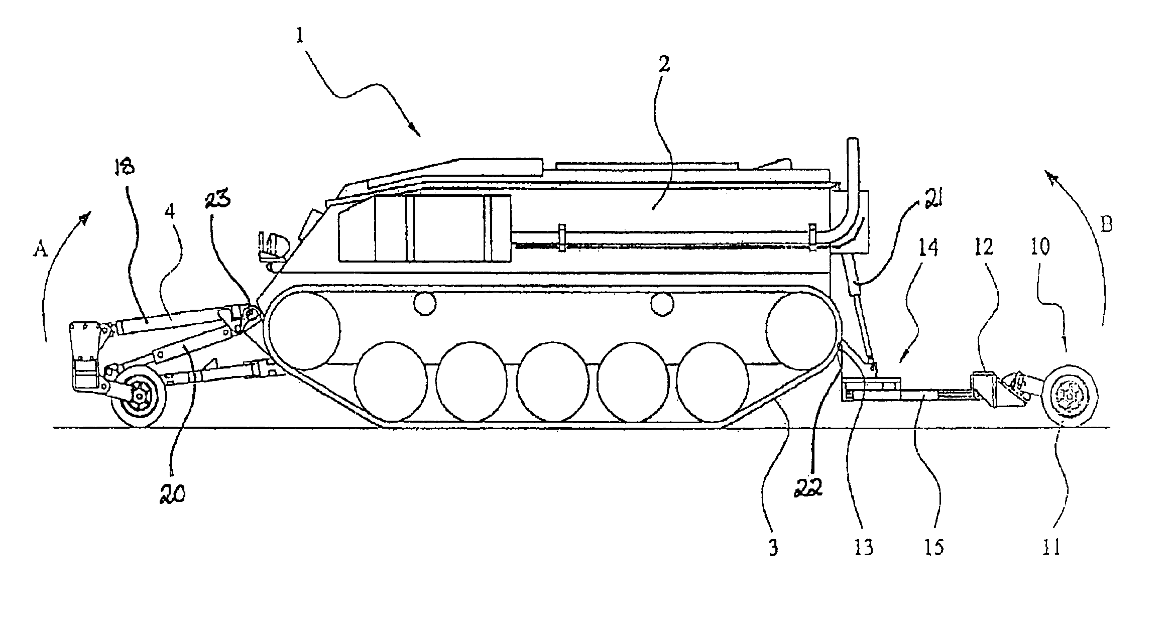
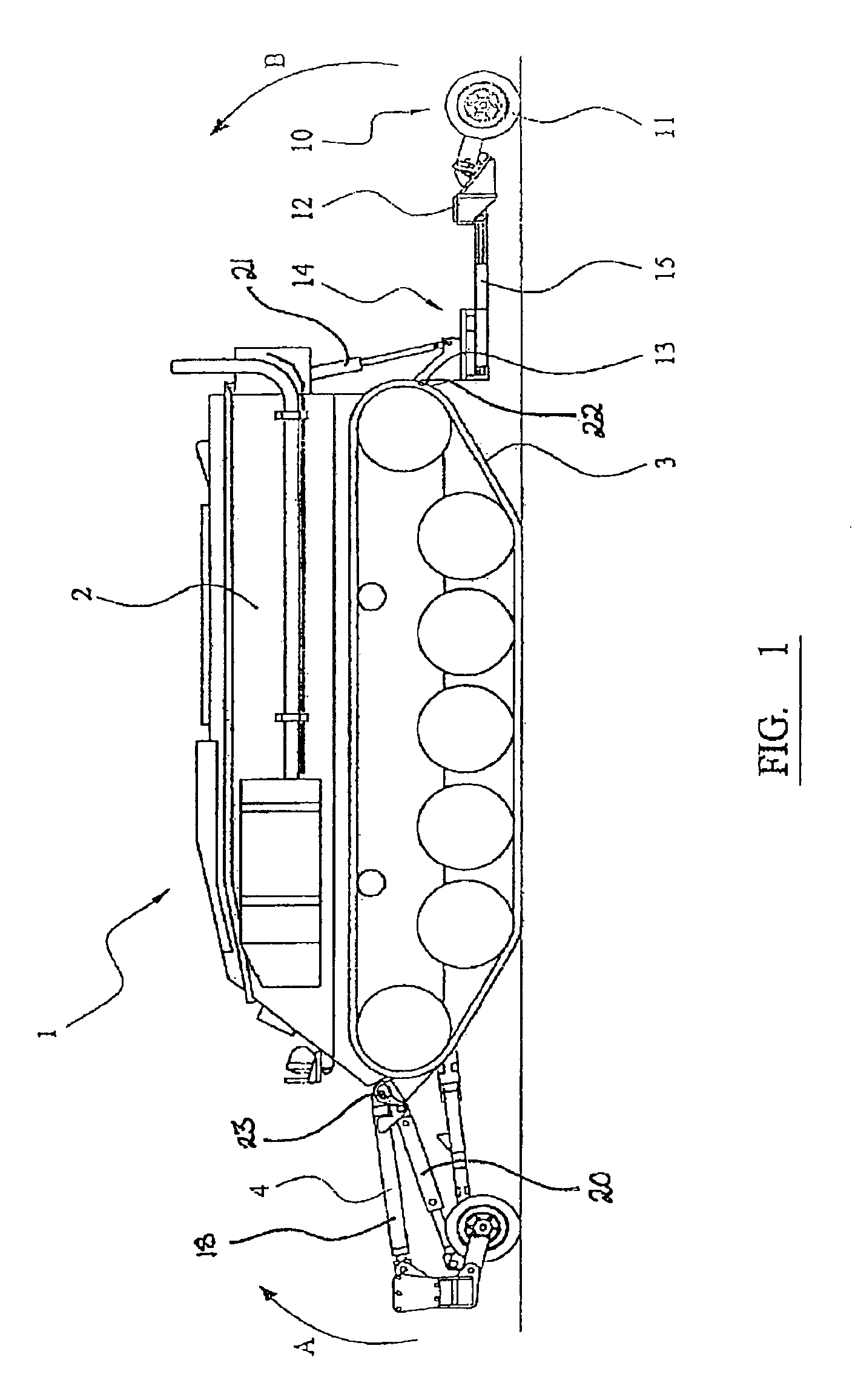
[0013]By providing at least one second roller assembly adapted to be mounted behind the vehicle to apply pressure to the ground behind the vehicle, this provides the advantage that mines between the wheels or tracks of the vehicle can be detonated, and the downward force applied to the or each second roller assembly can counteract the downward force applied to the or each first roller assembly, thus minimising tilting of the vehicle. Furthermore, by providing guide means for maintaining the position of the or each said first roller assembly forwardly of the respective wheel or track of the vehicle, this provides the advantage that the apparatus is also effective when the vehicle is travelling around a curved path.
[0015]This provides the advantage that the guide means can be constructed in a relatively simple manner such that the position of the or each first roller assembly relative to the body of the vehicle is automatically controlled by the position of the body of the vehicle relative to the or each second roller assembly.
[0021]This provides the advantage that if a roller assembly should become damaged because of detonating a mine, the roller assembly can be jettisoned from within the vehicle with the minimum amount of danger to personnel.
[0026]This provides the advantage that the or each roller assembly can castor and / or take account of variations in the height of the ground.
[0029]This provides the advantage of enabling the roller to accommodate variations in the height of the ground.

Problems solved by technology

Mine detonating apparatus of this type suffers from the drawback that while the heavy sacrificial mine rollers can readily be fitted to battle tanks (weighing approximately 40 to 60 tonne), they are too heavy to be carried on armoured personnel carriers, which generally weigh only approximately 10 to 20 tonne.
However, this arrangement suffers from the drawback that they are only effective when the vehicle is travelling in a relatively straight line, and only operate across the width of the track or wheel of the vehicle and not the region between the tracks or wheels.
It is not feasible to modify the prior art rollers to operate across the entire width of the front of the vehicle, since it would not be possible to make front rollers of such width castor, thus significantly impairing the mobility of the vehicle, and the vehicle would have to apply a downward force of about 3.5 tonne to the forward roller assembly to enable the roller assembly to apply the necessary force of about 5 tonne to the ground.
This would cause undesirable upward movement of the front of the vehicle.

Method used


Image

  • Mine detonating apparatus and vehicle including such apparatus
  • Mine detonating apparatus and vehicle including such apparatus
  • Mine detonating apparatus and vehicle including such apparatus

Examples


Embodiment Construction

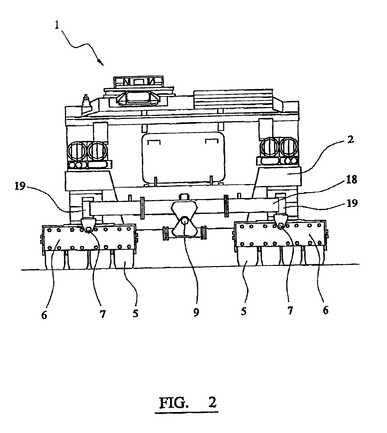
[0038]Referring to FIGS. 1 to 3, an armoured personnel carrier 1 comprises a vehicle body 2 supported on a pair of tracks 3. A front roller assembly 4 is arranged forwardly of each of the tracks 3 and each roller assembly 4 consists of a set of four solid rubber wheels 5, each of which is independently sprung in order to accommodate differences in the height of the ground.

[0039]The wheels 5 of the front roller assemblies 4 are mounted to supports 6, and each support 6 is connected via horizontal and vertical pivots 7 to a support frame 8. The support frame B is pivotable about a horizontal pivot 9 to accommodate unevenness in the ground. The wheels 5 and supports 6 are attached in such a way that the supports 6 shear from the support frame 8 in the event of a mine detonating against one of the wheels 5 with sufficient force, and the supports 6 are also attached to the vehicle by means of hydraulically retractable pins 22, 23 so that the wheels 5 can be jettisoned when damaged withou...


PUM


Abstract

A mine detonating apparatus to be mounted to an armoured personnel carrier (1) is disclosed. A front roller assembly (4) is mounted at the front of a vehicle body (2) of the armoured personnel carrier (1) to apply pressure to the ground forwardly of each track (3) of the armoured personnel carrier (1). A rear roller assembly (10) is mounted rearwardly of the vehicle body (3) to apply pressure to the ground behind the vehicle, the front and rear rollers (4, 10) being pre-loaded. The rear roller assembly (10) is connected to the vehicle body by means of hydraulic cylinders (15, 16) and a support frame (8) supporting the front roller assemblies (4) is connected to the vehicle body (2) by of a pair of hydraulic cylinders (17, 18). The hydraulic cylinders (15, 16, 17, 18) are arranged to maintain the position of the front roller assemblies forwardly of the respective tracks (3).

Description

BACKGROUND AND FIELD OF THE INVENTION[0001]The present application claims the priority of a United Kingdom patent filed Jul. 3, 2000 under application No. 0016402.0.[0002]The present invention relates to mine detonating apparatus and vehicles including such apparatus. The invention relates particularly, but not exclusively, to mine detonating apparatus for use with armoured personnel carriers.[0003]In many situations, such as peacekeeping operations and low intensity conflicts, there is a:requirement for military or peacekeeping personnel to be able to travel along roads which may be mined.[0004]A mine detonating apparatus for use with battle tanks is known. The apparatus includes a pair of heavy rollers known as mine rollers), each of which is located in front of a track of the tank. As the tracks of the tank approach a mine, the weight of the rollers detonates the mine. These rollers are made of steel and are sufficiently strong that they are able to withstand the blast.[0005]Mine...

Claims


Application Information

Patent Timeline
IPC IPC(8): F41H11/16F41H11/00
CPCF41H11/30
Inventor RENWICK, PETER JOHNEMMERSON, GRAHAM
Owner PEARSON ENG
Learn More