Display device for vehicle

a technology for a display device and a vehicle, which is applied in the direction of machines/engines, instruments, transportation and packaging, etc., can solve the problems of inability to obtain sufficient visual effects, complicated construction of japanese patents, and large cost, and achieves a wide display area, easy to see, and good external appearance of small display portions

Inactive Publication Date: 2005-07-12
CALSONIC KANSEI CORP
View PDF18 Cites 23 Cited by
  • Summary
  • Abstract
  • Description
  • Claims
  • Application Information

AI Technical Summary

Benefits of technology

[0014]According to another aspect of the present invention, an instrument for a vehicle includes an indicating needle disposed rotatably along a surface of a plate with characters, and a transparent cover is disposed separately from the plate in the surface side of the plate, In addition, a small display portion is disposed in the transparent cover portion with a floating state. Therefore, a new visual effect having a stereoscopic feeling can be obtained because the small display portion can be seen as the floating state to a surface of the small display portion.
[0015]The small display portion is disposed in a position which is overlapped with a base portion of the indicating needle of transparent cover. By disposing the small display portion in the position which is overlapped with the base portion of the indicating needle, the small display portion can be disposed in a portion which can be seen easily and does not disturb the plate.
[0016]The small display portion is contained in a housing, and an outside face of the housing and a base portion of the indicating needle are arranged approximately concentrically, or the outside face of the housing is constructed to have a larger diameter than the base portion of the indicating needle. A good external appearance of the small display portion can be obtained by arranging the outside face of the housing for containing

Problems solved by technology

However, the instrument for the vehicle according to the above-mentioned Japanese Patent Laid Open is complicated to construct and

Method used


Image

  • Display device for vehicle
  • Display device for vehicle
  • Display device for vehicle

Examples


Embodiment Construction

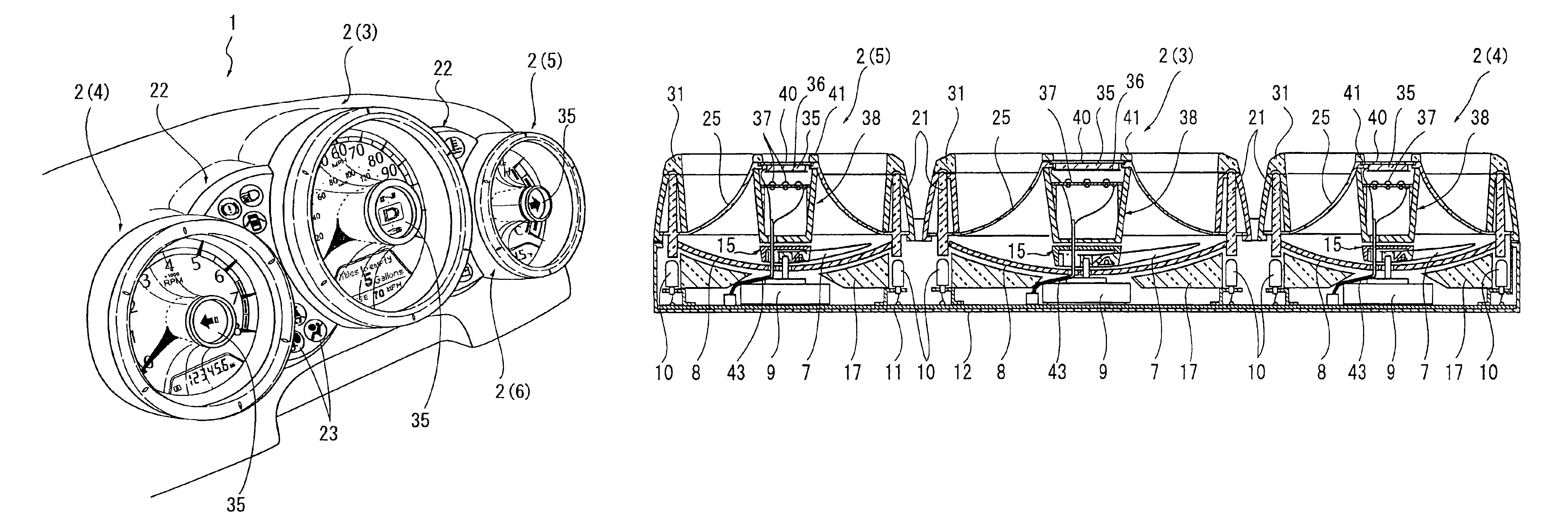
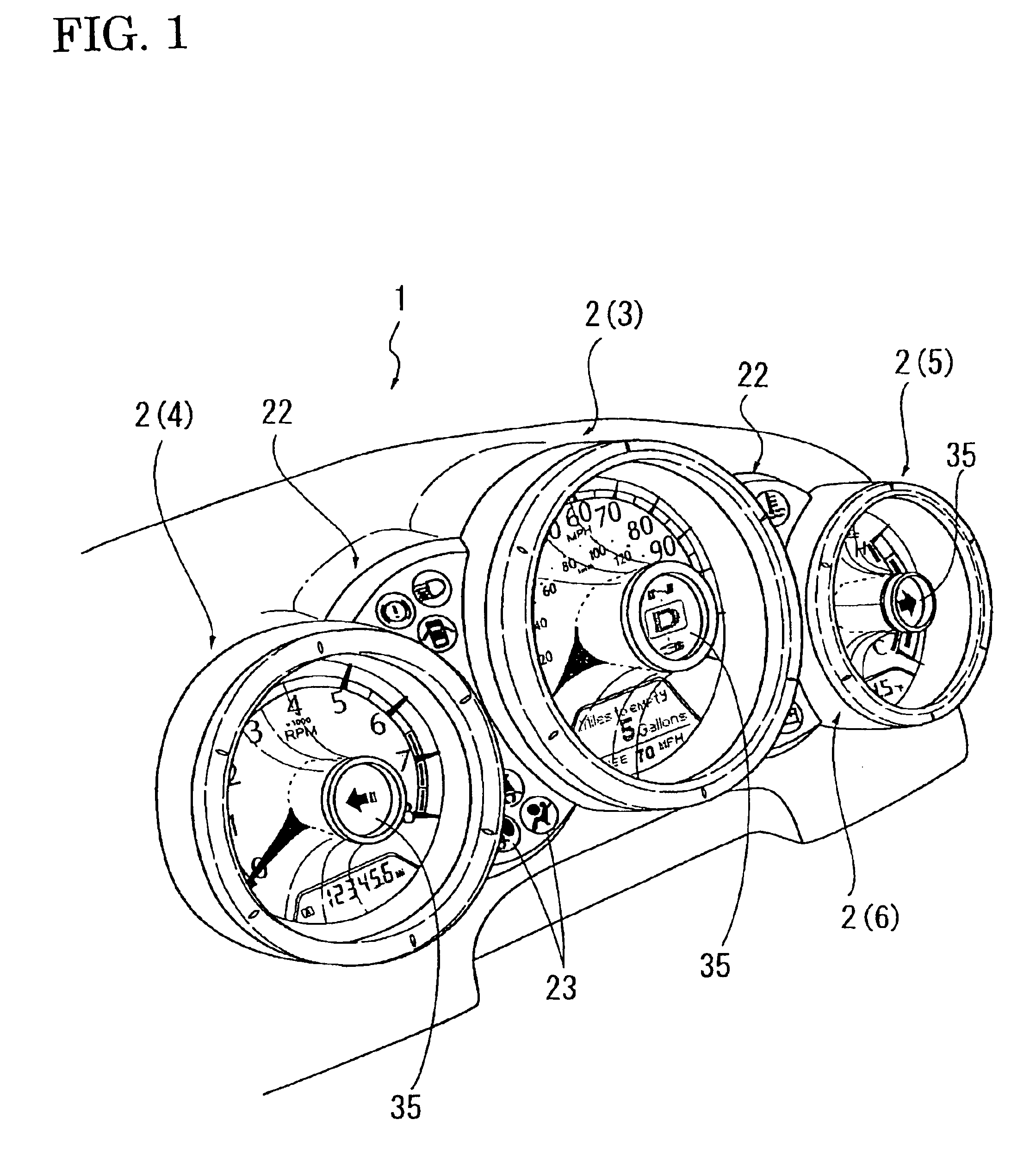
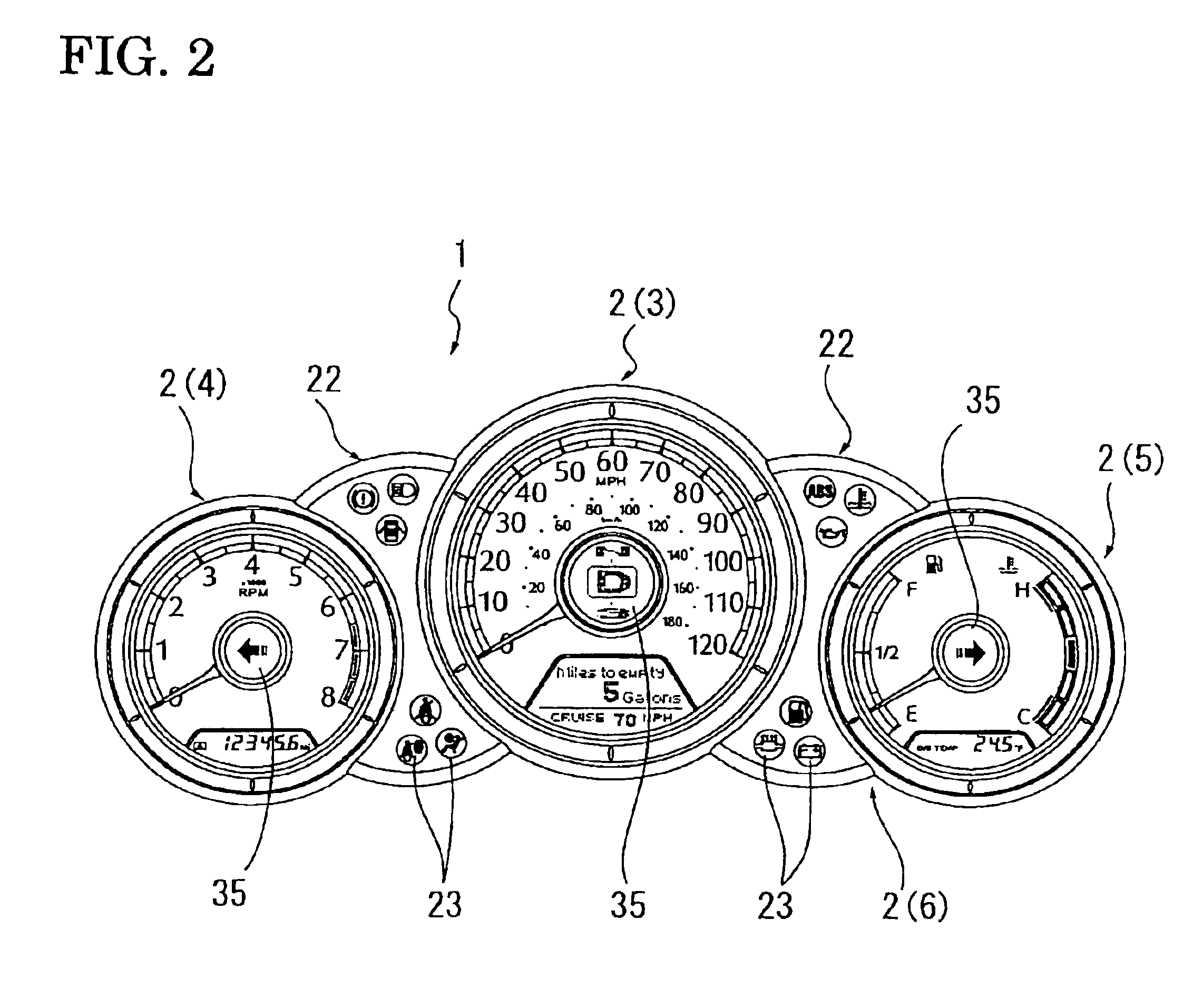
[0025]Embodiments of the present invention will be described as follows with reference to the drawings. First of all, a configuration will be explained. A front part of a passenger compartment in a vehicle such as an automobile and so on is provided with an instrument panel P. Such an instrument panel is provided with an indicating instrument or an instrument for a vehicle 1 as shown in FIGS. 1 and 2. This indicating instrument or this instrument for the vehicle 1 comprises a plurality of instrument parts 2. Each of the instrument parts 2 consists of, for example a speed meter 3, a tachometer 4, a coolant temperature gauge 5, a fuel gauge 6 and so on.

[0026]Each of the instrument parts 2 comprises a base 11 which includes a plate having a surface on which characters are provided 8 having a rotation area of an indicating needle 7, a movement 9 which rotates the indicating needle 7, and a light source 10 of LED or the like for illuminating as shown in FIGS. 3 to 5.

[0027]The base 11 is ...


PUM


Abstract

A display device for a vehicle comprises an instrument for a vehicle (1), which includes a plate having a surface on which characters are provided (8), an indicating needle (7) rotatably disposed along a surface of the plate (8), and a transparent cover (25) disposed in a surface side of the plate (8) separately from the plate (8), and a small display portion (35) is disposed in a portion of the transparent cover (25) to be a floating state to the plate (8), and a new visual effect having a stereoscopic feeling can be obtained because the small display portion (35) can be seen as the floating state to the surface of the plate (8).

Description

BACKGROUND OF THE INVENTION[0001]1. Field of the Invention[0002]The present invention relates to a display device for a vehicle such as an instrument panel.[0003]2. Description of the Prior Art[0004]For a vehicle such as an automobile, an instrument panel portion of a front part of a passenger compartment panel is provided with an indicating instrument (an instrument for a vehicle) having a plurality of instrument parts such as a speed meter, a tachometer, a coolant temperature gauge, an odometer, a trip meter, and so on.[0005]In such an instrument, the peripheral of the instrument is configured to emit a ring-shaped light as described in Japanese Patent Laid-Open 2002-81966.[0006]However, the instrument for the vehicle according to the above-mentioned Japanese Patent Laid Open is complicated to construct and requires many parts at a significant cost.[0007]Moreover, as described in Japanese Patent Laid-Open 2000-108722, there is provided an instrument for a vehicle including a small...

Claims


Application Information

Patent Timeline
IPC IPC(8): B60K37/02
CPCB60K37/02B60K2350/1064B60K2350/203B60K2370/154B60K2370/33B60K2370/698
Inventor NAKAGAWA, YASUYUKISATO, SHIGEYUKI
Owner CALSONIC KANSEI CORP
Why Eureka
Try Eureka