Image forming device customizing the image to fit the paper length

a technology of image forming and paper length, which is applied in the direction of electrographic process, recording apparatus, instruments, etc., can solve the problems of dirty carrying belt, and the like, and achieve the effect of not wasteful consumption of toner

Inactive Publication Date: 2005-07-12
OKI ELECTRIC IND CO LTD
View PDF29 Cites 4 Cited by
  • Summary
  • Abstract
  • Description
  • Claims
  • Application Information

AI Technical Summary

Benefits of technology

[0006]In view of the above, it is an object of the present invention to provide a tandem-type image forming device which can be realized by using only one paper edge detecting sensor and one detecting circuit and which, even if paper that is shorter than usual is inserted, does not transfer an image to a place outside the paper. That is, the image is not transferred to a carrying belt, a carrying unit such as a carrying roller, or the like, thus enabling the carrying belt not to be made dirty and toner not to be wastefully consumed and, by temporarily stopping counting even while printing is being done, printing even on a sheet of paper having a length larger than a pre-determined one is made possible without a hitch.

Problems solved by technology

However, the conventional tandem-type image forming device has problems to be solved as described below.
As a result, either the carrying belt is made dirty, or toner is wasteflully consumed.

Method used


Image

  • Image forming device customizing the image to fit the paper length
  • Image forming device customizing the image to fit the paper length
  • Image forming device customizing the image to fit the paper length

Examples


first embodiment

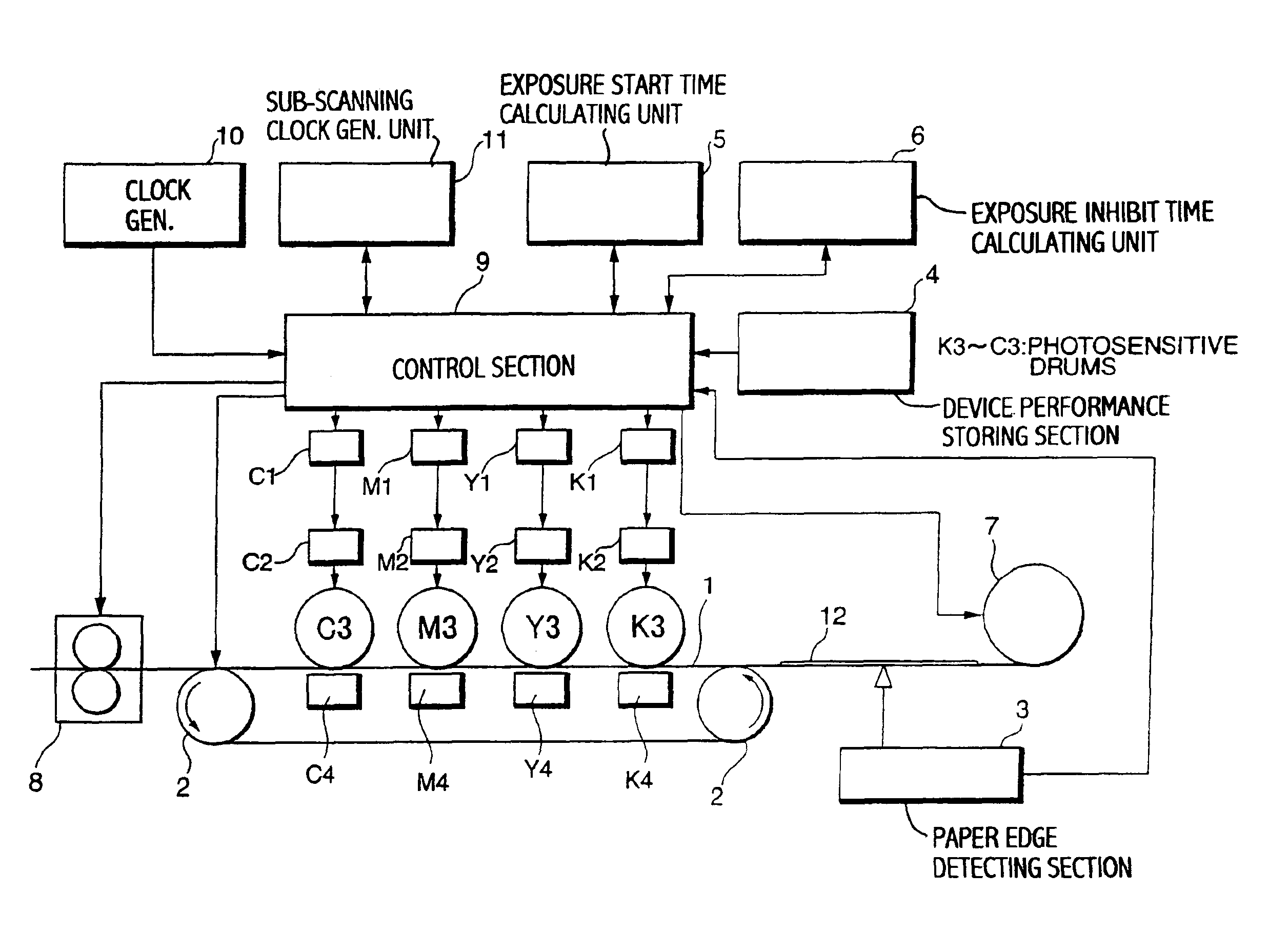
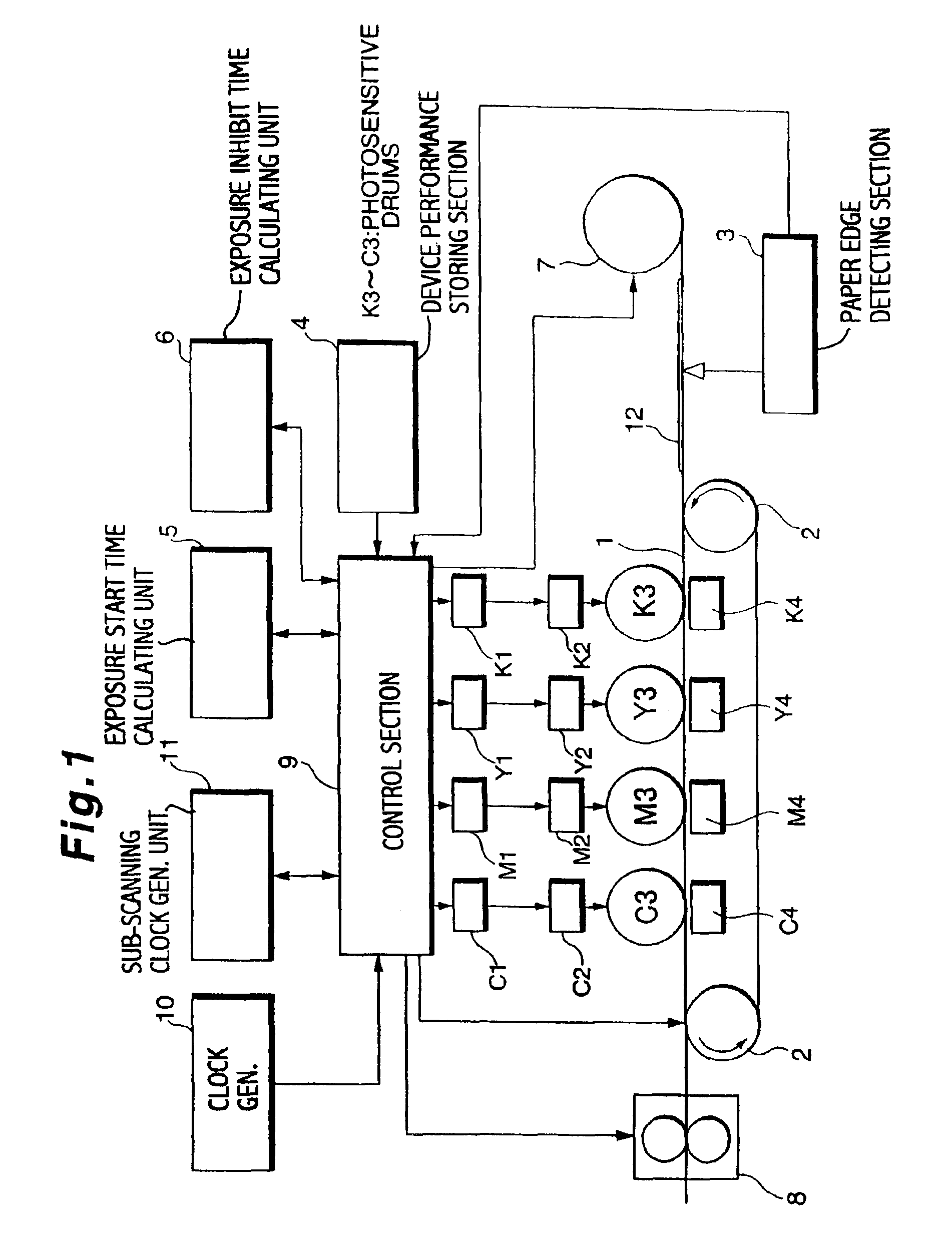
[0064]FIG. 1 is a schematic block diagram showing configurations of an image forming device according to a first embodiment of the present invention. The image forming device of the first embodiment as shown in FIG. 1 includes a carrying belt 1, a carrying roller 2, a paper edge detecting section 3, a device performance storing section 4, an exposure starting time calculating unit 5, an exposure inhibiting time calculating unit 6, a paper feeding roller 7, a fixing device 8, a control section 9, a clock generator 10, a sub-scanning clock generating unit 11, and LED controlling units K1, Y1, M1, and C1, exposure units K2, Y2, M2, and C2, photosensitive drums K3, Y3, M3, and C3, and transfer devices K4, Y4, M4, and C4.

[0065]The carrying belt 1 operates as a carrying path to carry a sheet of paper 12 at a predetermined carrying speed along which the photosensitive drums K3, Y3, M3, and C3 and the transfer device K4, Y4, M4, and C4, and a like are arranged at preset intervals. The carry...

second embodiment

[0117]FIG. 4 is a schematic block diagram showing configurations of an image forming device according to a second embodiment of the present invention. The image forming device of the second embodiment as shown in FIG. 4 includes a carrying belt 1, a carrying roller 2, a paper edge detecting section 3, a device performance storing section 4, a paper feeding roller 7, a fixing device, a clock generator 10, a sub-scanning clock generating unit 11, an image data feeding supply start time calculating unit 21, a blank data supplying time calculating unit 22, a control section 23, LED controlling units K1, Y1, M1, and C1, exposure devices K2, Y2, M2, and C2, photosensitive drums K3, Y3, M3, and C3, and transfer devices K4, Y4, M4, and C4.

[0118]Only configurations of the image forming device of the second embodiment of the present invention being different from the first embodiment will be described. The image data supplying start time calculating unit 21, when having received an edge detec...

third embodiment

[0146]FIG. 6 is a schematic block diagram showing configurations of an image forming device according to a third embodiment of the present invention. The image forming device of the third embodiment as shown in FIG. 3 includes a carrying belt 1, a carrying roller 2, a paper edge detecting section 3, a device performance storing section 4, a fixing device 8, a clock generator 10, a sub-scanning clock generating unit 11, a page data transfer starting unit 31, a page data transfer time measuring unit 32, a count stopping unit 33, a control section 34, a delay time storing section 35, LED controlling units K1, Y1, M1, and C1, exposure devices K2, Y2, M2, and C2, photosensitive drums K3, Y3, M3, and C3, and transfer devices K4, Y4, M4, and C4.

[0147]Only configurations of the image forming device of the third embodiment of the present invention being different from the first embodiment will be described. Moreover, in the first and second embodiments, the present invention is explained in ...


PUM


Abstract

A tandem-type image forming device is provided which includes a plurality of photosensitive drums, a paper edge detecting section to detect a front edge and a rear edge of a sheet of paper, an exposure starting time calculating unit for each of a plurality of photosensitive drums, an exposure inhibiting time calculating unit to inhibit printing, when paper having a length being smaller than a predetermined length of the paper is inserted, on a portion being shorter than preset paper, and a control section to control an entire image forming device. By configuring as above, the tandem-type image forming device can be realized by using only one paper edge detecting sensor and only one detecting circuit. Even when paper having a length being smaller than a preset length of the paper is inserted, no transfer of an image to a place outside of the paper, that is, to a carrying belt occurs.

Description

BACKGROUND OF THE INVENTION[0001]1. Field of the Invention[0002]The present invention relates to a tandem-type image forming device, such as a color print engine.[0003]2. Description of the Related Art[0004]In a conventional tandem-type image forming device, generally, a method is employed in which a plurality of image forming units are arranged in a paper carrying direction. The image forming units include photosensitive drums. In such the method, an edge of a sheet of paper is detected for every image forming unit. Print timing is determined for each photosensitive drum based on the time of detecting an edge of a sheet of paper, the position of each of the image forming units, and the carrying speed of the sheet of paper, and printing is initiated sequentially to transfer an image to the sheet of paper.[0005]However, the conventional tandem-type image forming device has problems to be solved as described below. That is, each of the image forming units has to be provided with a pap...

Claims


Application Information

Patent Timeline
Patent Type & Authority Patents(United States)
IPC IPC(8): B41J11/42B41J13/00G03G15/01B41J29/38G03G21/00G03G21/14H04N1/00
CPCB41J11/42B41J13/0054
Inventor NAKASENDO, TAKASHI
Owner OKI ELECTRIC IND CO LTD
Why Eureka
Try Eureka