
Reference mark, method for recognizing reference marks and method for object measuring

a reference mark and reference mark technology, applied in the field of reference marks, can solve the problems of limited value range (code depth) of the ring coding system employed widely in practice, inconvenient increase of data or value range, and inability to recognize reference marks, etc., to achieve robust and flexible, recognize particularly quickly and accurately

Inactive Publication Date: 2005-07-12
DAIMLER AG
View PDF10 Cites 31 Cited by
  • Summary
  • Abstract
  • Description
  • Claims
  • Application Information

AI Technical Summary

Benefits of technology

The technical effect of this patent is to provide an efficient way to recognize reference marks quickly and reliably. This method uses a process that works well when measuring objects. Additionally, it provides a specific type of reference mark that is easy to identify.

Problems solved by technology

The technical problem addressed in this patent text relates to improving the accuracy and efficiency of identifying reference marks used in industrial applications through the use of flexible and adaptable encoding techniques that account for common issues like rotational and scaling distortion, as well as variations in background noise levels. Additionally, the patent seeks to reduce errors caused by misrecognizing reference markers, which can lead to significant errors in evaluating the underlying task at hand.

Method used


Image

  • Reference mark, method for recognizing reference marks and method for object measuring
  • Reference mark, method for recognizing reference marks and method for object measuring
  • Reference mark, method for recognizing reference marks and method for object measuring

Examples


Embodiment Construction

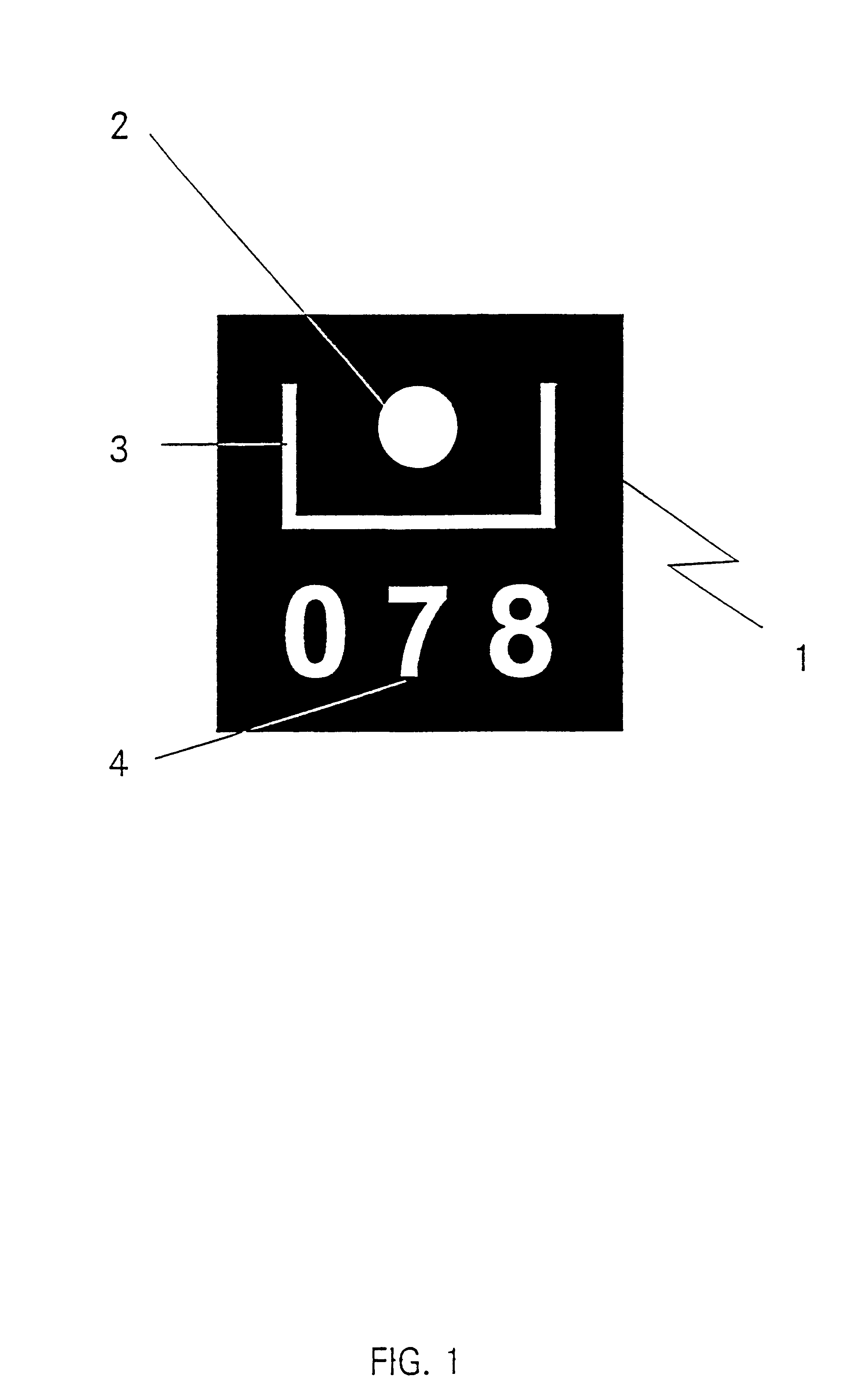
[0034]One such reference mark 1 is shown (enlarged) in FIG. 1. It includes a surveying character 2 in the shape of a circular area, an orientation character 3 in the shape of a U, in the center of which the surveying character is situated, and of which the cross-segment is significantly longer than the side segments, and encoded characters 4 in the shape of three numbers of uniform size, which are provided in a fixed separation below the cross-segment of the U.

[0035]The object provided with reference marks is recorded as a gray value image from various positions using optical digital cameras. By means of 3-D correspondence analysis, the 3D coordinates of the object are compared against the pixel-coordinates of an image of the object.

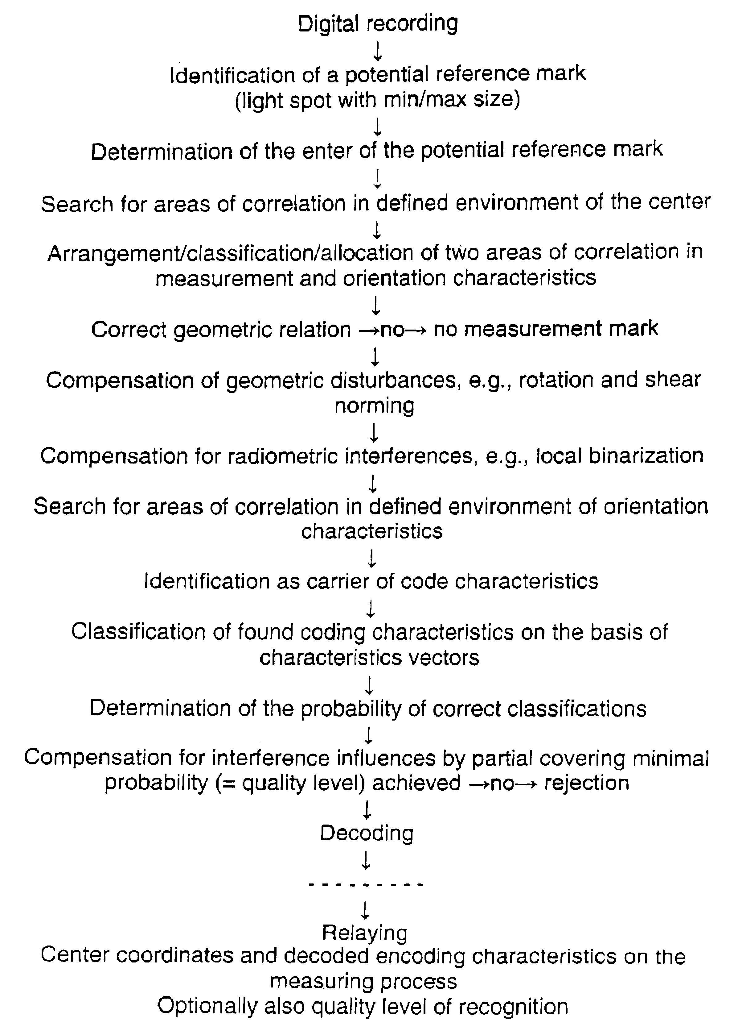
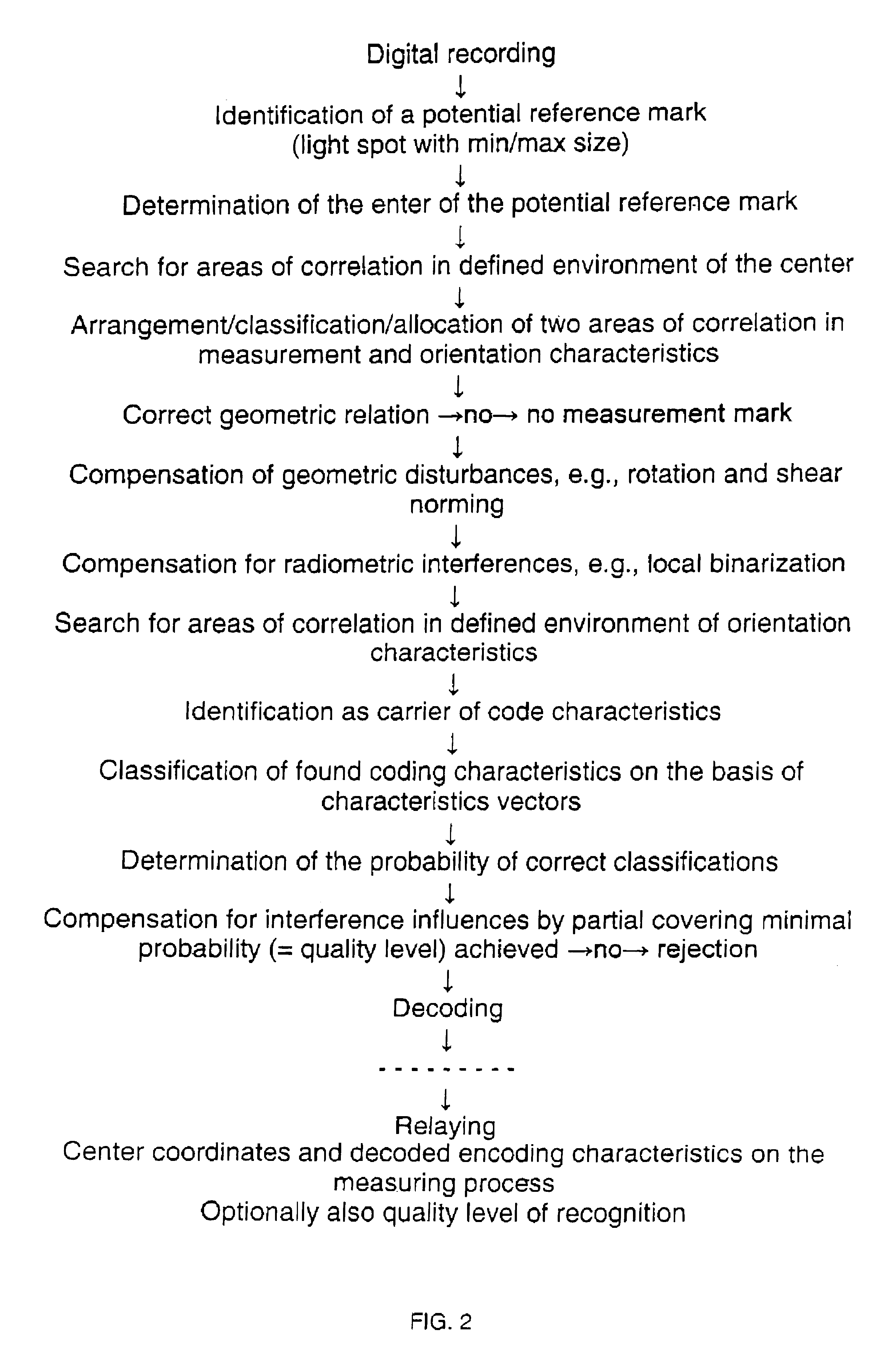
[0036]Potential reference marks are detected within the total picture. These could be actual reference marks or merely supposed reference marks, for example reflected light or other light disturbances. For these potential reference marks, the pixel coord...


PUM


Abstract

The invention relates to a reference mark, a method for recognizing reference marks and a method for object measuring. According to the invention, the object is fitted with coded reference marks. Said marks are automatically recognized and decoded by the inventive method for reference mark recognition, whereupon a three-dimensional representation of the object is realized. According to the invention, the method compensates automatically for geometrical and radiometric interferences and generates at least one quality measurement to evaluate the quality of recognition and decoding. The invention particularly enables fast recognition and decoding of large numbers of reference marks and fast measuring of objects.

Description


Claims


Application Information

Patent Timeline
Owner DAIMLER AG
Learn More