
Photovoltaic fabric with woven bus architecture

a technology of photovoltaic fabric and bus structure, which is applied in the direction of weaving, selvedges, textiles and paper, etc., can solve the problem of not being able to bus the electrical curren

Active Publication Date: 2019-04-25
PEPIN TECH LLC
View PDF7 Cites 1 Cited by
  • Summary
  • Abstract
  • Description
  • Claims
  • Application Information

AI Technical Summary

Benefits of technology

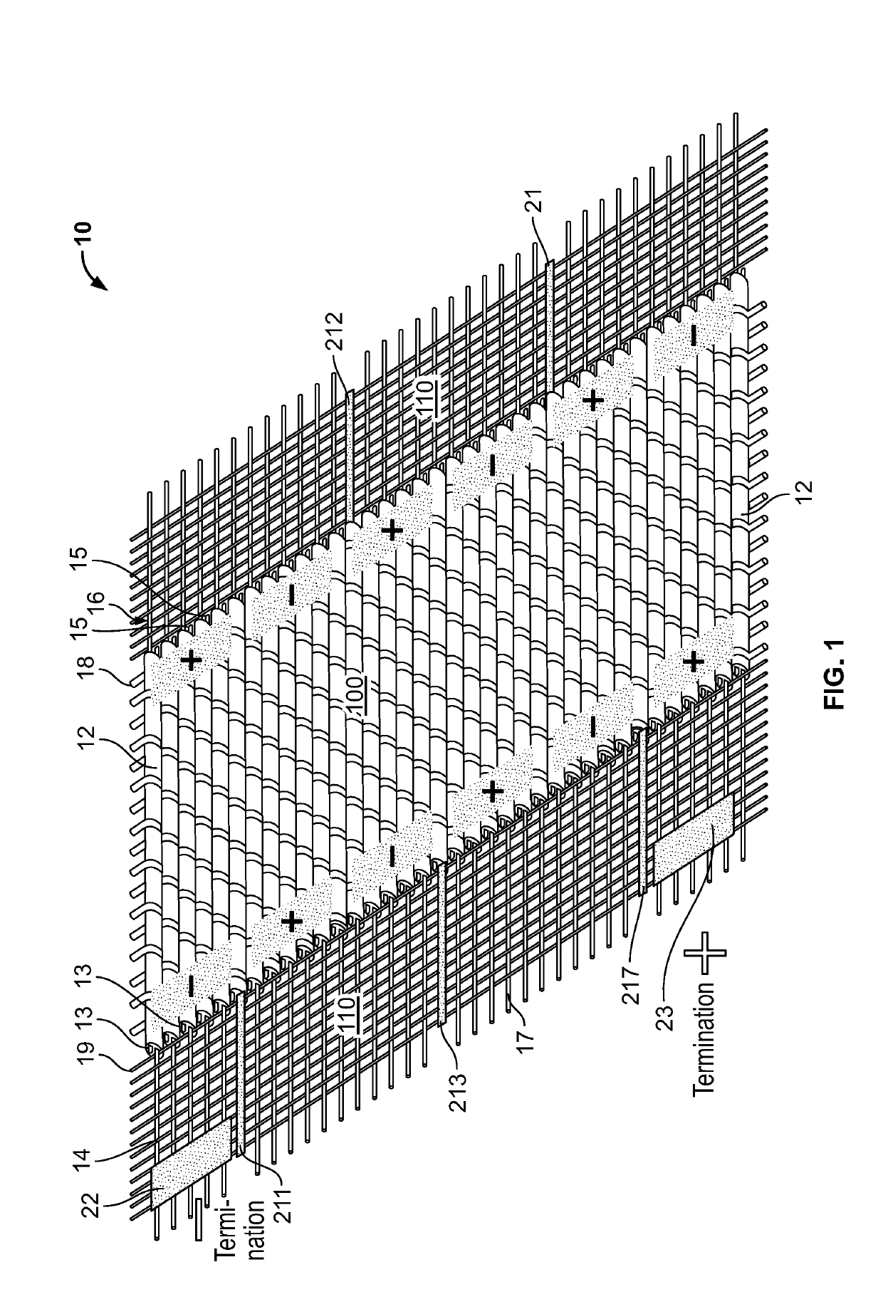
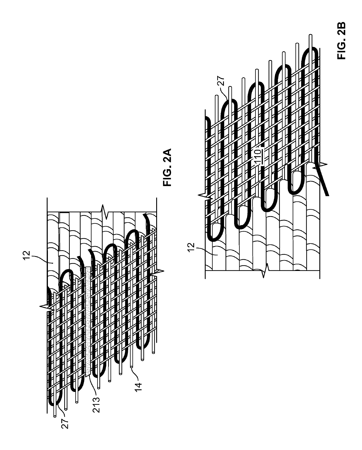
The invention provides a flexible and robust bus architecture for a fabric made from PV filaments that allows for the connection of the fabric filaments in various electrical circuit configurations. The invention also provides a method for weaving a conductive bus structure into the selvage edge of a PV fabric that is both flexible and robust. The PV weft elements comprise a terminated negative electrode and a terminated positive electrode, and each electrode is surrounded by an insulator to prevent short circuits. The insulators may be made of shrink-fit tubing or a liquid polymer. The invention ensures that the fabric is safe and efficient for use in various applications.

Problems solved by technology

While the aforesaid Chittibabu disclosures contemplate incorporating PV filaments into a fabric, to date there has not been a viable means for busing the electrical current generated by a plurality of PV filaments in a fabric, or for incorporating the filaments into a fabric to construct parallel and series circuits to obtain a desired voltage and current.

Method used


Image

  • Photovoltaic fabric with woven bus architecture
  • Photovoltaic fabric with woven bus architecture
  • Photovoltaic fabric with woven bus architecture

Examples


example 1

[0033]A total of three hundred (300) feet of 2-stranded PV filament are woven into the weft of a fabric with a PV active area approximately twelve (12) inches in length. The fabric measures approximately eight (8) inches in height. This fabric is configured with six (6) series groups of fifty (50) parallel PV filaments.

[0034]The fabric generates approximately sixty (60) mA of DC current at three (3) VDC. It is sewn into a backpack and charges a battery which powers an infrared camera for search and rescue operations.

example 2

[0035]A total of one thousand (1000) feet of 2-stranded PV filament are woven into the weft of a fabric with a PV active area approximately twelve (12) inches in width. The fabric measures approximately twenty-six (26) inches in length. This fabric is configured with ten (10) series groups of one hundred (100) parallel PV filaments. The fabric generates approximately sixty (120) mA of DC current at five (5) VDC. It comprises the back panel of a soldier's uniform and charges batteries for cell phones, radios and computers.

example 3

[0036]A total of ten thousand (10000) feet of 2-stranded PV filament are woven into the weft of a fabric with a PV active area approximately forty-eight (48) inches in width. The fabric measures approximately fifty (50) inches in length. This fabric is configured with ten (10) series groups of two hundred fifty (250) parallel PV filaments. The fabric generates approximately twelve hundred (1200) mA, (or 1.2 A) of DC current at five (5) VDC. It comprises the side panel of a military tent and powers LED lighting, computer tablets and cellular phone chargers.


PUM


Abstract

A fabric comprising a plurality of photovoltaic filaments includes a conductive bus structure woven into the selvage edge of the fabric, providing a robust and flexible electrical connection from the positive and negative electrode leads of the photovoltaic filaments. The bus structure may be formed in segments which can include any combination of series and parallel configurations to accommodate loads requiring specified voltage and current.

Description

FIELD OF THE INVENTION[0001]The invention relates to a fabric incorporating photovoltaic filaments and particularly to a fabric having an electrical busing architecture woven into the selvage edge of the fabric.BACKGROUND OF THE INVENTION[0002]A photovoltaic (“PV”) device or element, as used herein, means any device incorporating a material that generates electrical current from incident radiation. Current is drawn from the device via the device positive electrode and negative electrode.[0003]Flexible photovoltaic filaments are known in the art, as described for example in Patent Application Publication U.S. 2007 / 0079867 and U.S. Pat. No. 7,622,667, to Chittibabu, which are incorporated by reference.[0004]While the aforesaid Chittibabu disclosures contemplate incorporating PV filaments into a fabric, to date there has not been a viable means for busing the electrical current generated by a plurality of PV filaments in a fabric, or for incorporating the filaments into a fabric to con...

Claims


Application Information

Patent Timeline
Patent Type & Authority Applications(United States)
IPC IPC(8): H01L31/02H01L31/05H01L31/0352H01L31/0216D03D1/00D03D13/00
CPCH01L31/0201H01L31/0508H01L31/035281H01L31/02167D03D1/0076D03D13/004D10B2401/18D10B2401/16H01L31/042D03D5/00Y02E10/50H10K30/53
Inventor PEPIN, KARL A.
Owner PEPIN TECH LLC
Learn More