Architectural molding

a technology of architectural molding and molding parts, applied in the direction of walls, building repairs, transportation and packaging, etc., can solve the problems of substantial skill and relatively high cost of materials for molding installation

Inactive Publication Date: 2005-07-19
NOMACO
View PDF61 Cites 36 Cited by
  • Summary
  • Abstract
  • Description
  • Claims
  • Application Information

AI Technical Summary

Problems solved by technology

In general, such materials are relatively expensive and installation of the molding has required substantial skill as a workman.

Method used


Image

  • Architectural molding
  • Architectural molding
  • Architectural molding

Examples


Embodiment Construction

[0027]When a range such as 5-25 is given, this means preferably at least 5 and preferably not more than 25.

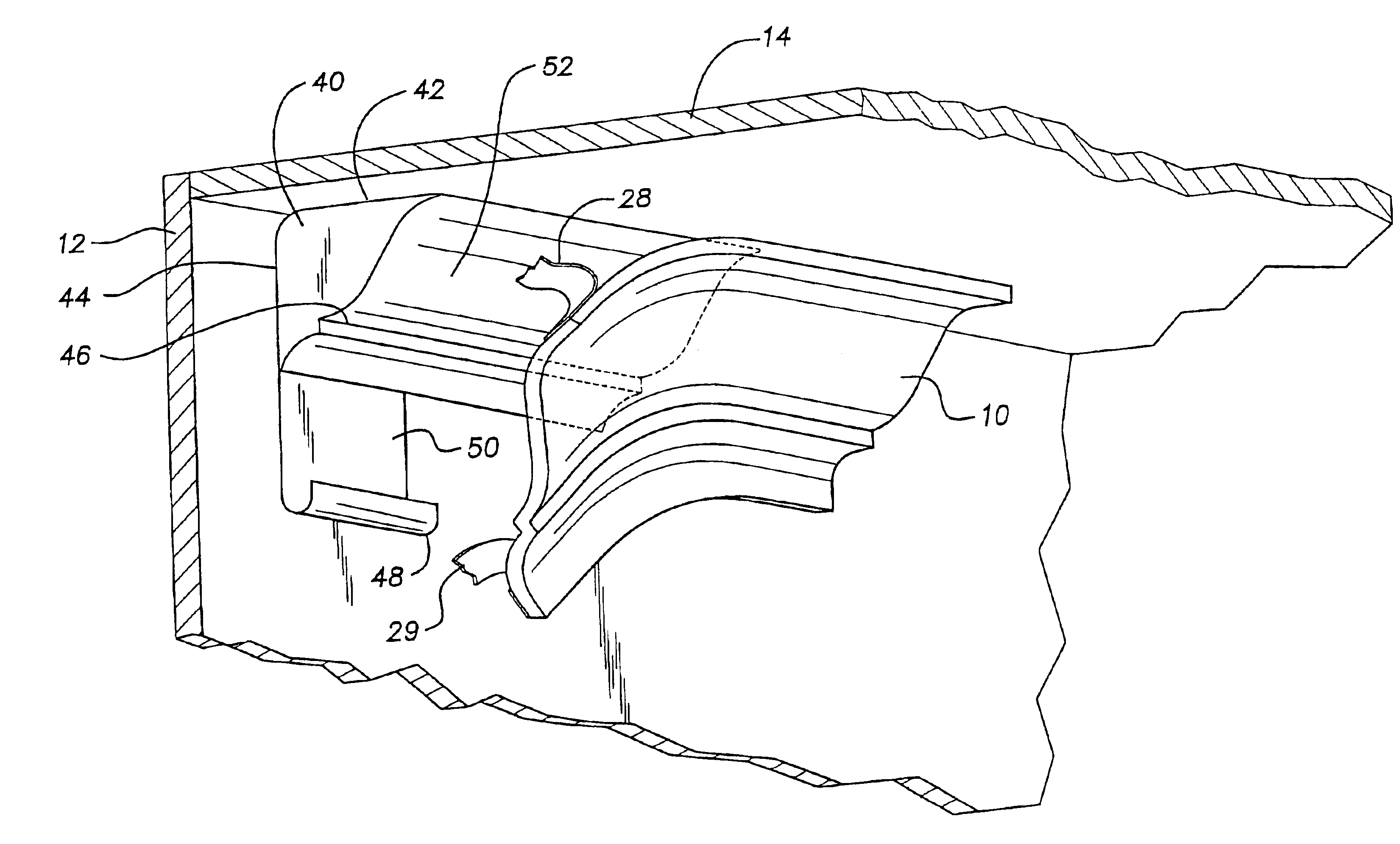
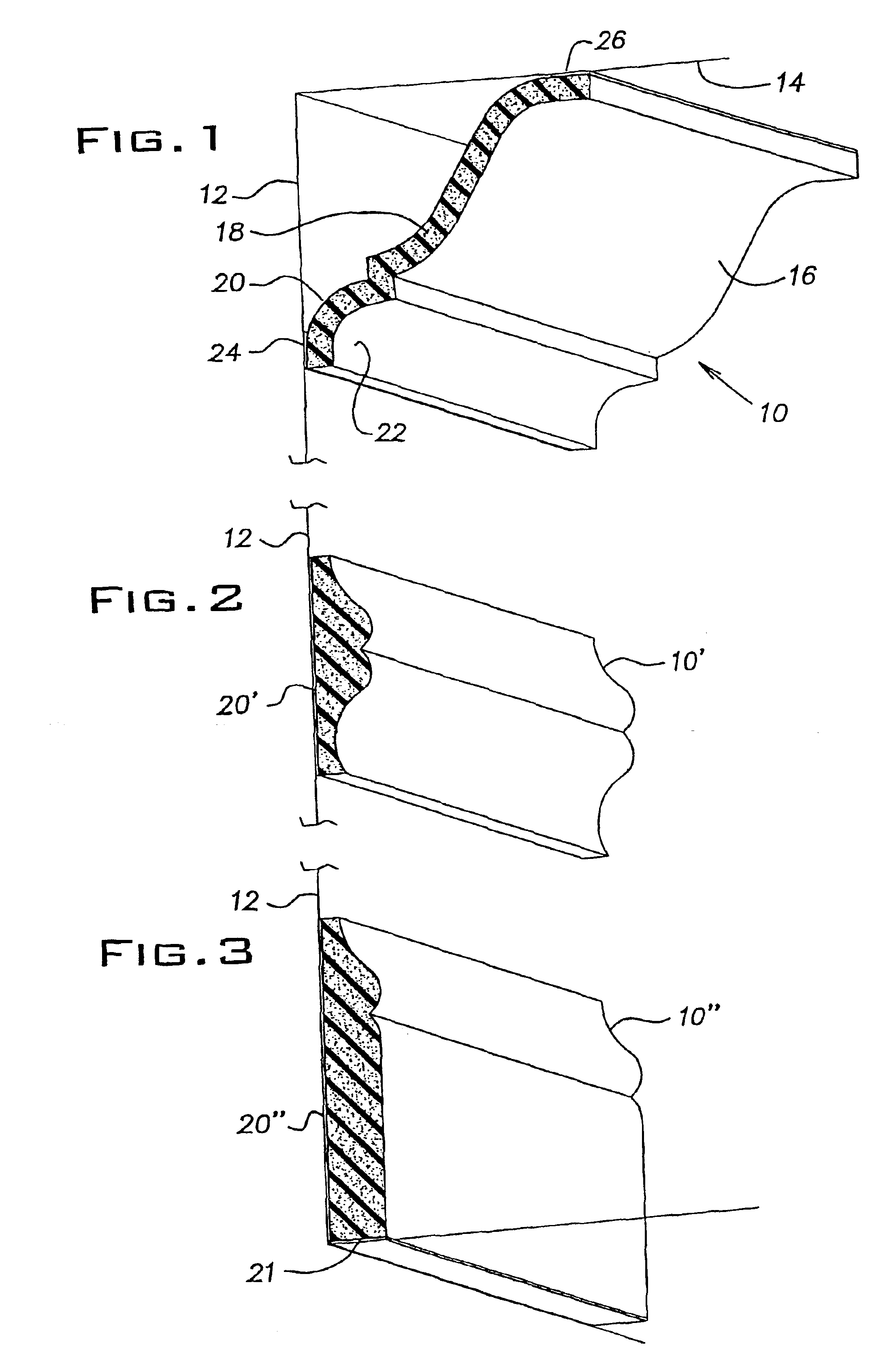
[0028]Referring to FIG. 1, an architectural molding 10 is shown installed between a top portion of a wall 12 and the edge of a ceiling 14. Moldings at this location are often referred to as crown moldings. The molding 10 includes an extruded flexible plastic foam member 16 having a cross section or cross sectional profile 18 and a rear side or surface 20 and a front side or surface 22. The front side or surface 22, when viewed in cross section (such as looking down the longitudinal length of the molding), determines the front surface profile of the molding. Correspondingly, the rear side or surface 20 determines or defines a rear surface profile. In the preferred embodiment, the cross sectional profile 18 is constant along the longitudinal direction of the member 16; that is, if you look at the cross sectional profile 18 every few feet as you travel down the length of member 16...


PUM

PropertyMeasurementUnit
lengthaaaaaaaaaa
diameteraaaaaaaaaa
lengthaaaaaaaaaa

Abstract

An architectural molding (10) includes an extruded flexible plastic foam member (16) having a front side (22), a rear side (20) and a cross sectional profile (18). Also included is a layer of pressure sensitive adhesive (24, 26) affixed to at least a portion of the rear side and a release strip (28, 29) releasibly adhered to the layer of pressure sensitive adhesive.

Description

BACKGROUND OF THE INVENTION[0001]This invention relates to architectural molding installed at the base, mid-portion or top of an architectural wall and, in particular, to a molding composed of flexible plastic foam.[0002]Decorative moldings are routinely used in architecture to provide decoration and to cover various raw edges and imperfections. Such moldings are most commonly made of wood, but other rigid materials have been employed. In general, such materials are relatively expensive and installation of the molding has required substantial skill as a workman.[0003]U.S. Pat. No. 5,496,512 shows thin molded plastic (e.g., polystyrene) molding strips for application to walls. The molding strips rely on thinness to provide flexibility and are either vacuum or pressure molded. A central portion of the molding is attached to the wall and one or more of the edges of the molding are resiliently flexed into snug engagement with the wall. The molding is installed using overlapped joints. T...

Claims


Application Information

Patent Timeline
Patent Type & Authority Patents(United States)
IPC IPC(8): E04F19/04E04B1/00E04B2/00E04C1/00E04F13/00
CPCE04F19/0436E04F19/0477E04F19/0495Y10T428/1476E04F2019/0454Y10S52/01E04F2019/0413E04F2019/0427
Inventor MAURER, SCOTT D.
Owner NOMACO
Why Eureka
Try Eureka