Optimization of building ventilation by system and zone level action

a technology of building ventilation and system level action, applied in the direction of fire alarms, instruments, heating types, etc., can solve the problems of correspondingly higher than necessary energy costs, and achieve the effect of increasing the amount of supply airstream flow

Active Publication Date: 2005-07-19
TRANE INT INC
View PDF17 Cites 79 Cited by
  • Summary
  • Abstract
  • Description
  • Claims
  • Application Information

AI Technical Summary

Benefits of technology

[0008]It is an object, feature and advantage of the present invention to provide a cohesive strategy for selecting building ventilation control strategy. A further object, feature and advantage of the present invention automatically selects and implements a second control strategy if a control element of the selected control strategy is unavailable or invalid. A still further object, feature and advantage of the present invention is that the selected strategy is reselected and implemented should the unavailable control element be repaired or recover and present a valid signal.
[0009]The present invention provides a method of selecting a ventilation control strategy from among a plurality of ventilation control strategies. The method comprises the steps of: determining if a CO2 signal is present and valid; selecting a CO2 based ventilation control strategy if the CO2 signal is present and valid; selecting a second ventilation control strategy if the CO2 signal is not present or is invalid; and operating using the selected strategy. The selection occurs in a zone controller.
[0010]The present invention also provides a method of coordinating operation in a building control system including a coordinating controller, a plurality of coordinated controllers, and a communications network operably connecting the coordinating controller to the plurality of coordinated controllers. The method comprises the steps of: maintaining database and system information in the coordinating controller; completing system control strategy calculations in the coordinating controller; disseminating information relative to system control strategies from the coordinating controller to the plurality of coordinated controllers; and determining in at least one of the plurality of coordinated controllers which of a selected group of control strategies to be implemented in that coordinated controller.
[0011]The present invention further provides a method of coordinating the operation of a building control system having a coordinating controller and a plurality of coordinated controllers. The method comprises the steps of: determining at least one system wide control strategy in the coordinating controller; forwarding elements of the system wide control strategy to one or more of a plurality of coordinated controllers; implementing one or more forwarded requirements of the system wide control strategy in at least one of the plurality of coordinating controllers; and overriding, in at least one of the plurality of coordinated controllers, at least one forwarded element of the system wide control strategy.
[0012]The present invention additionally provides a method of coordinating the operation of a building control system including a coordinating controller and a plurality of coordinated controllers. The method comprises the steps of: providing a plurality of coordinated controllers; providing a coordinating controller operably connected to and communicating with the plurality of coordinated controllers; determining a system wide control strategy in the coordinating controller; communicating elements of the system wide control strategy to the plurality of coordinated controllers; determining local requirements in at least one of the plurality of coordinated controllers; and overriding the normal control routines of the coordinating controller if said at least one of the plurality of coordinated controllers determines that local requirements will not be met by the system wide strategy.
[0013]The present invention still further provides a method of calculating an outside air requirement for a zone. The method comprises the steps of: determining that ventilation is on for the particular zone; verifying that a CO2 signal is present and valid for the particular zone; controlling the airflow to the zone based on the CO2 signal if the signal is present and valid; and controlling the airflow to the zone based on another criteria if the CO2 signal is not present or is invalid.

Problems solved by technology

As a result, at least some spaces in the building are over ventilated leading to correspondingly higher than necessary energy costs.
Problems in these systems occur when CO2 or occupancy sensors fail or provide invalid signals or when occupancy schedules are not updated or entered correctly.

Method used


Image

  • Optimization of building ventilation by system and zone level action
  • Optimization of building ventilation by system and zone level action
  • Optimization of building ventilation by system and zone level action

Examples


Embodiment Construction

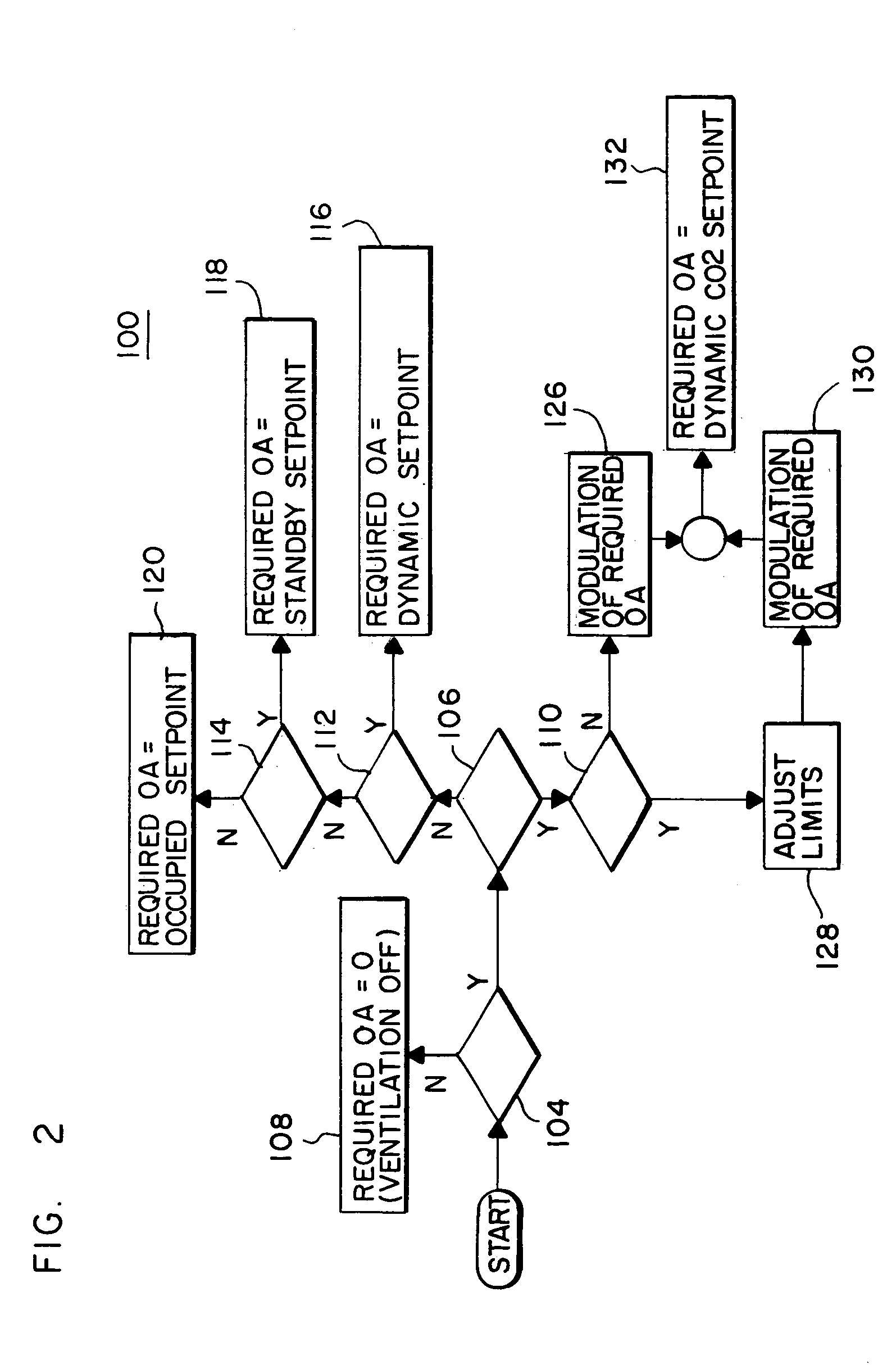
[0022]In the description which follows, like elements are marked throughout the specification and drawings with the same reference numerals, respectively. The drawing figures are not necessarily to scale, and flow diagrams or flow charts may show only essential steps of the improvements of the present invention. Conventional or ancillary operating steps may be omitted in the interest of clarity and conciseness. The letters Y and N in a flow chart mean “Yes” and “No” respectively.

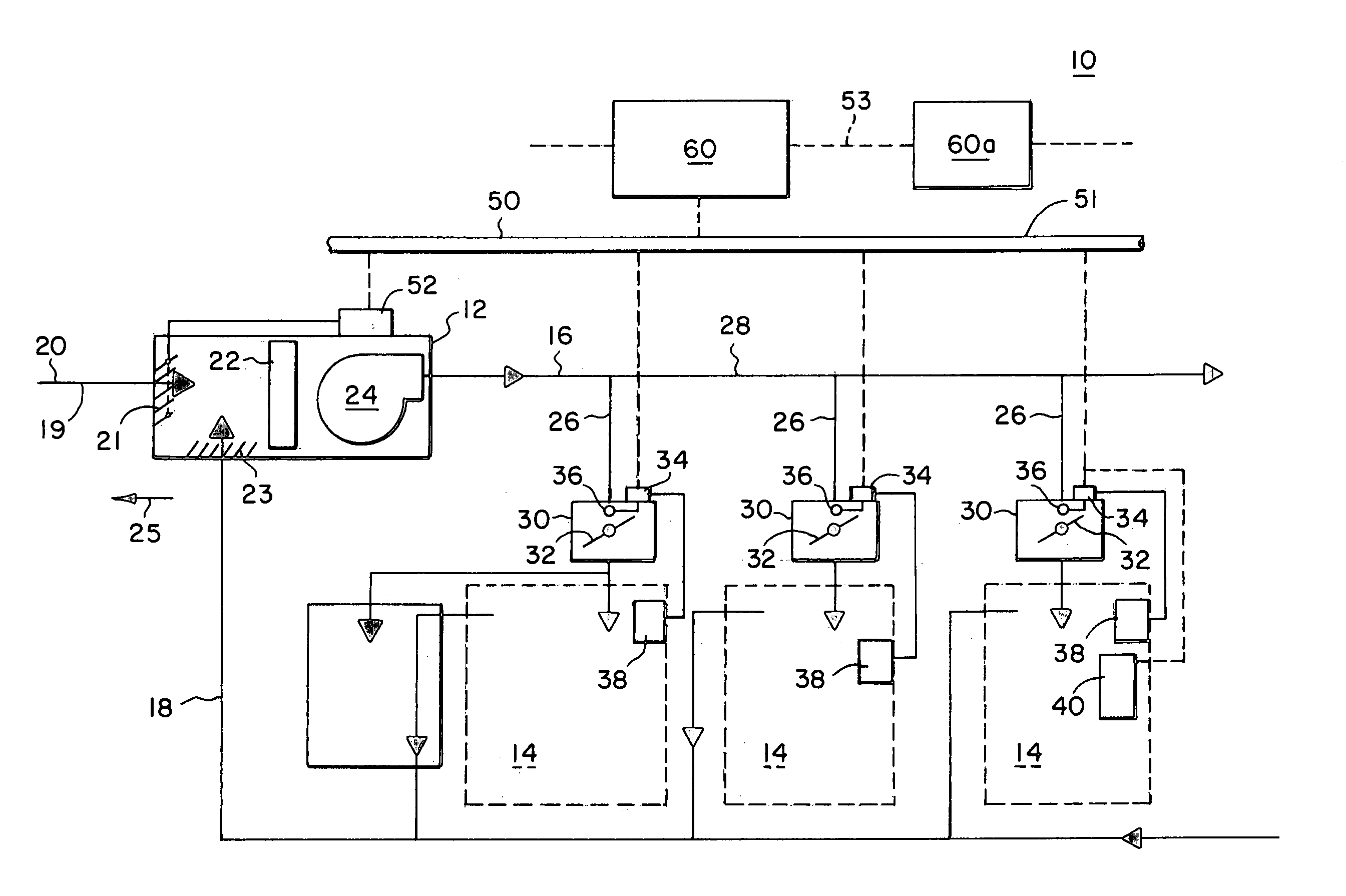
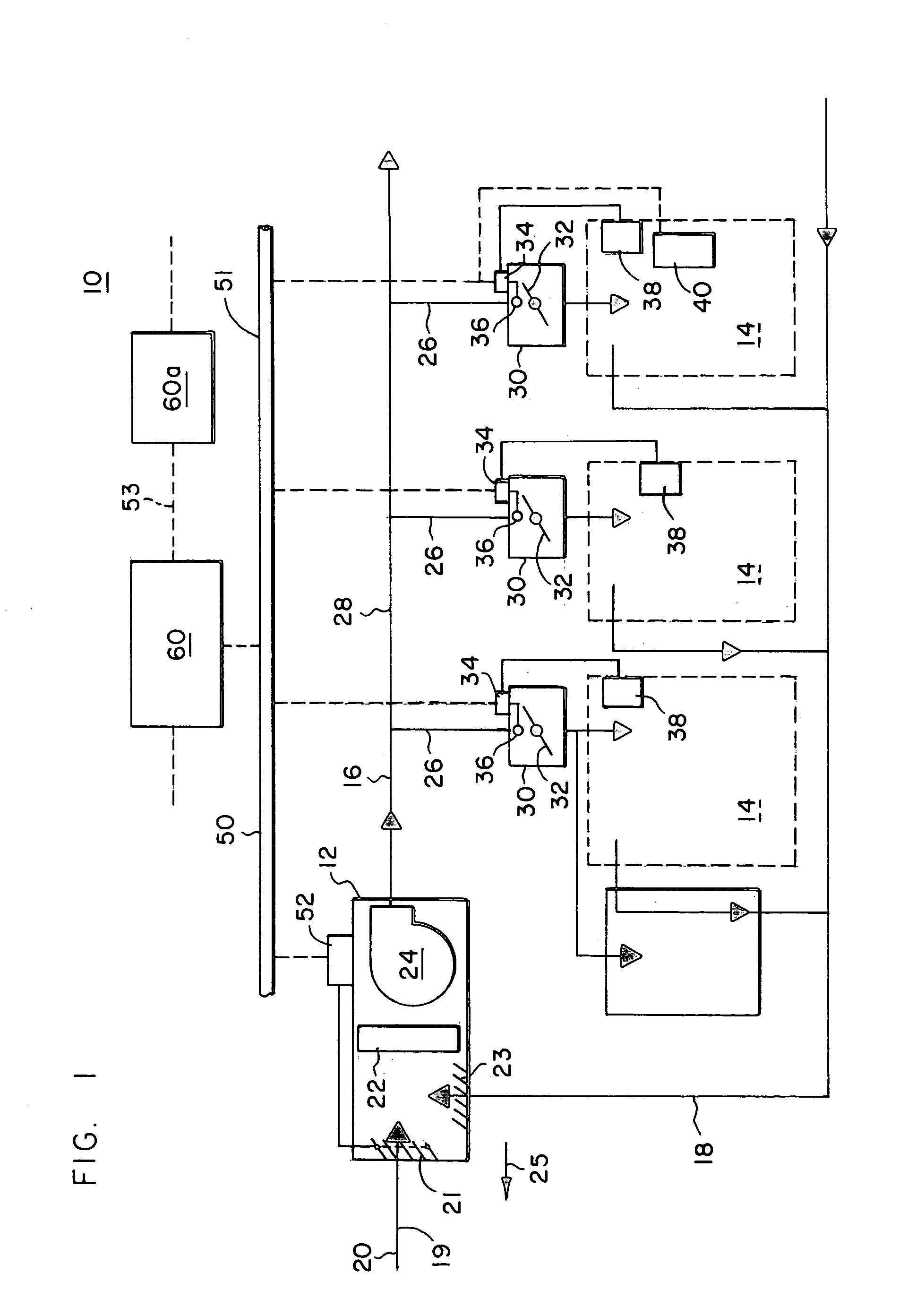
[0023]Referring to FIG. 1, a typical heating, ventilating and air conditioning (HVAC) air delivery / conditioning system 10 comprises an air handling unit 12 delivering conditioned air to a plurality of zones 14 by means of supply air ductwork 16 and receiving return air from those same zones 14 by means of return air ductwork 18.

[0024]For purposes of this invention, an air handler 12 is any apparatus comprising an enclosure that includes at least one piece of air handling equipment such as a blower, a heat ex...


PUM


Abstract

A method of selecting a ventilation control strategy from among a plurality of ventilation control strategies. The method comprises the steps of: determining if a CO2 signal is present and valid; selecting a CO2 based ventilation control strategy if the CO2 signal is present and valid; selecting a second ventilation control strategy if the CO2 signal is not present or is invalid; and operating using the selected strategy. The selection step occurs in a zone controller.

Description

BACKGROUND OF THE INVENTION[0001]A popular dictionary defines “ventilation” as the admission of “fresh air . . . to replace stale or noxious air”. In the context of a building, this means introducing outdoor air and circulating it throughout the building to dilute contaminants and odors. The amount of air needed for proper ventilation largely depends on the population of building. In most commercial applications, the number of people in the building seldom equals the design occupancy. As a result, at least some spaces in the building are over ventilated leading to correspondingly higher than necessary energy costs.[0002]Static rate ventilation is a control strategy where a particular ventilation rate is set and the particular rate does not vary to meet changing conditions.[0003]Various demand controlled ventilation strategies attempt to control ventilation based upon actual occupancy and reduce operating costs by optimizing or at least controlling the rate of outdoor air intake to s...

Claims


Application Information

Patent Timeline
Patent Type & Authority Patents(United States)
IPC IPC(8): F24F11/00
CPCF24F11/0001F24F11/0012Y02B30/78F24F2011/0038F24F2011/0067F24F2011/0026F24F11/30F24F2110/10F24F2110/70F24F2110/30F24F11/54Y02B30/70F24F11/58F24F11/61F24F2120/00F24F11/46
Inventor BLUNN, BRAD M.JOHNSON, TEDD P.SHEDIVY, EUGENE R.MCKEEVER, JAMES K.BJORKLUND, CHAD A.WATERCOTT, DWIGHT J.
Owner TRANE INT INC
Why Eureka
Try Eureka