Device and process for controlling a respirator

a technology of respirator and process, which is applied in the direction of valve operating means/release devices, applications, diagnostic recording/measuring, etc., can solve the problems of disadvantageous effect of these methods on patients, information on the frc and the change in the frc are usually unavailable,

Active Publication Date: 2006-11-23
DRAGERWERK AG
View PDF1 Cites 38 Cited by
  • Summary
  • Abstract
  • Description
  • Claims
  • Application Information

AI Technical Summary

Benefits of technology

[0007] The basic object of the present invention is to propose a device and a process for determining the change in the functional residual capacity (FRC) in a simple manner.
[0008] According to the invention, a process is provided for controlling a respirator in combination with a electroimpedance measuring device, which receives impedance measured signals U via a electrode application arranged on the upper body of a test subject. The process includes setting a mode for pressure-controlled or volume-controlled, mechanical respiration on the respirator during a first respiration phase. A first reference value Uref1 is calculated from the obtained end-expiratory values of the impedance measured signals U, which values are correlated with the respiration cycle. A second reference value Uref3 is formed from the end-expiratory values of the impedance measured signals U during another respiration phase during mechanical respiration. A difference is formed from the second reference value Uref3 and the first reference value Uref1 and is taken as an indicator of a change in the functional residual capacity (FRC) of the lung of the test subject (3).
[0009] According to another aspect of the invention, a respirator (ventilator) combined with an electroimpedance measuring device is provided. The combination includes an electrode application, which is arranged on the upper body of a test subject and detects impedance measured signals U. A control electronic unit is provided at the respirator for setting phases of respiration for pressure- or volume-controlled mechanical respiration. An evaluating unit is provided which calculates a first reference value Uref1 from the end-expiratory values of the impedance measured signals U during a first respiration phase and forms a second reference value Uref3 from the end-expiratory values of the impedance measured signals U during another respiration phase during mechanical respiration. The difference between the second reference value Uref3 and the first reference value Uref1 is an indicator of the change in the functional residual capacity (FRC) of the lung of the test subject.
[0010] The advantage of the present invention is essentially that a first reference value is formed from end-expiratory values of the impedance measured signals during a first phase of respiration for mechanical respiration. During the later phase of respiration, a second reference value is formed from the end-expiratory values of the impedance measured signals during mechanical respiration. The change in the functional residual capacity (FRC) of the test subject's lung is determined by comparing the reference values from the phases of respiration investigated. A noninvasive measurement method, which is not stressful for the test subject, and with which the local change in the lung volume can be determined, is available in electroimpedance tomography.
[0011] The relative change in impedance ΔZ / Zref is obtained in impedance tomography from the relative voltage changes ΔU / Uref on the body surface of the test subject, which develop during the different current feeds.
[0012] There is an alternation of inspiration and expiration during mechanical respiration, the change in impedance, ΔZ, therefore varies between an end-inspiratory value and an end-expiratory value.

Problems solved by technology

However, information on the FRC and the change in the FRC is usually unavailable.
A local FRC determination or FRC change can be estimated so far only by computed tomography and partly also by X-ray, with the known disadvantageous effects of these methods on the patient.

Method used


Image

  • Device and process for controlling a respirator
  • Device and process for controlling a respirator
  • Device and process for controlling a respirator

Examples


Embodiment Construction

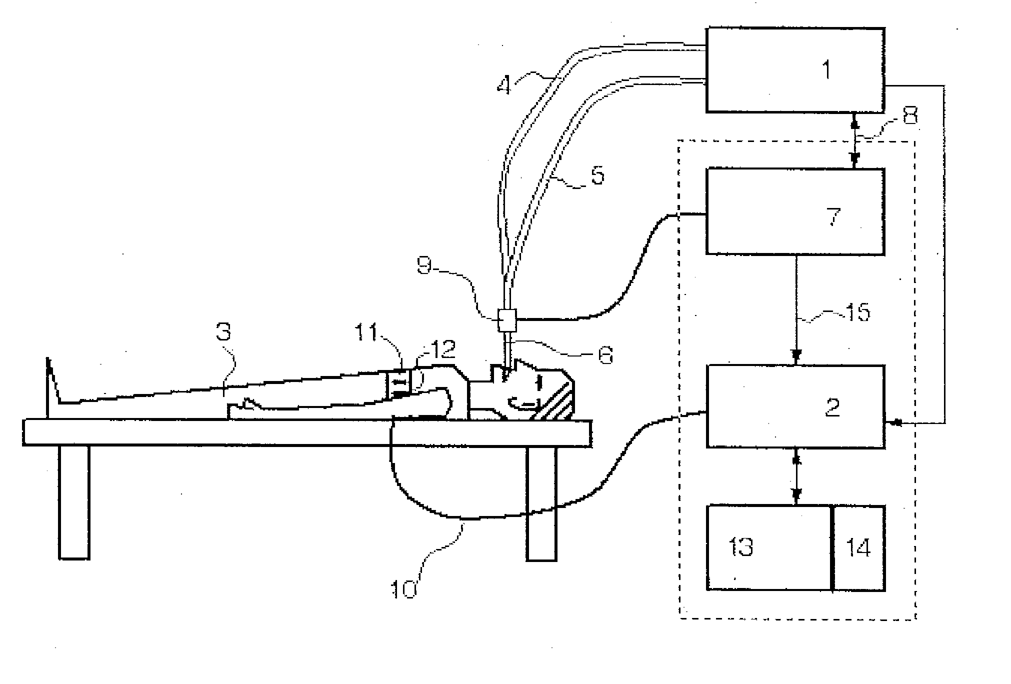
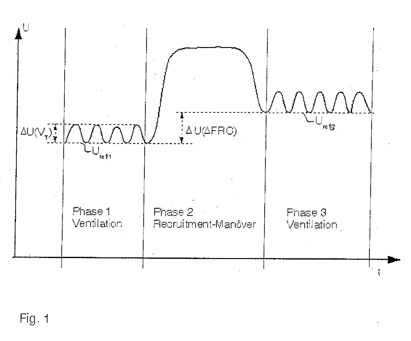
[0023] Referring to the drawings in particular, FIG. 1 schematically illustrates the course of impedance measured signals U during the alternation of mechanical respiration, respiration phase 1, at the time of a recruitment maneuver, respiration phase 2, and back to mechanical respiration, respiration phase 3.

[0024] An electroimpedance measurement is carried out during respiration phase 1 during as uniform respiration as possible. Since the tidal volume VT is known from the respirator, this can be used to determine the volume factor cv during respiration phase 1. After the end of the recruitment maneuver during respiration phase 2, the electroimpedance measurement is continued in respiration phase 3 in order to find possible differences in local ventilation compared to respiration phase 1.

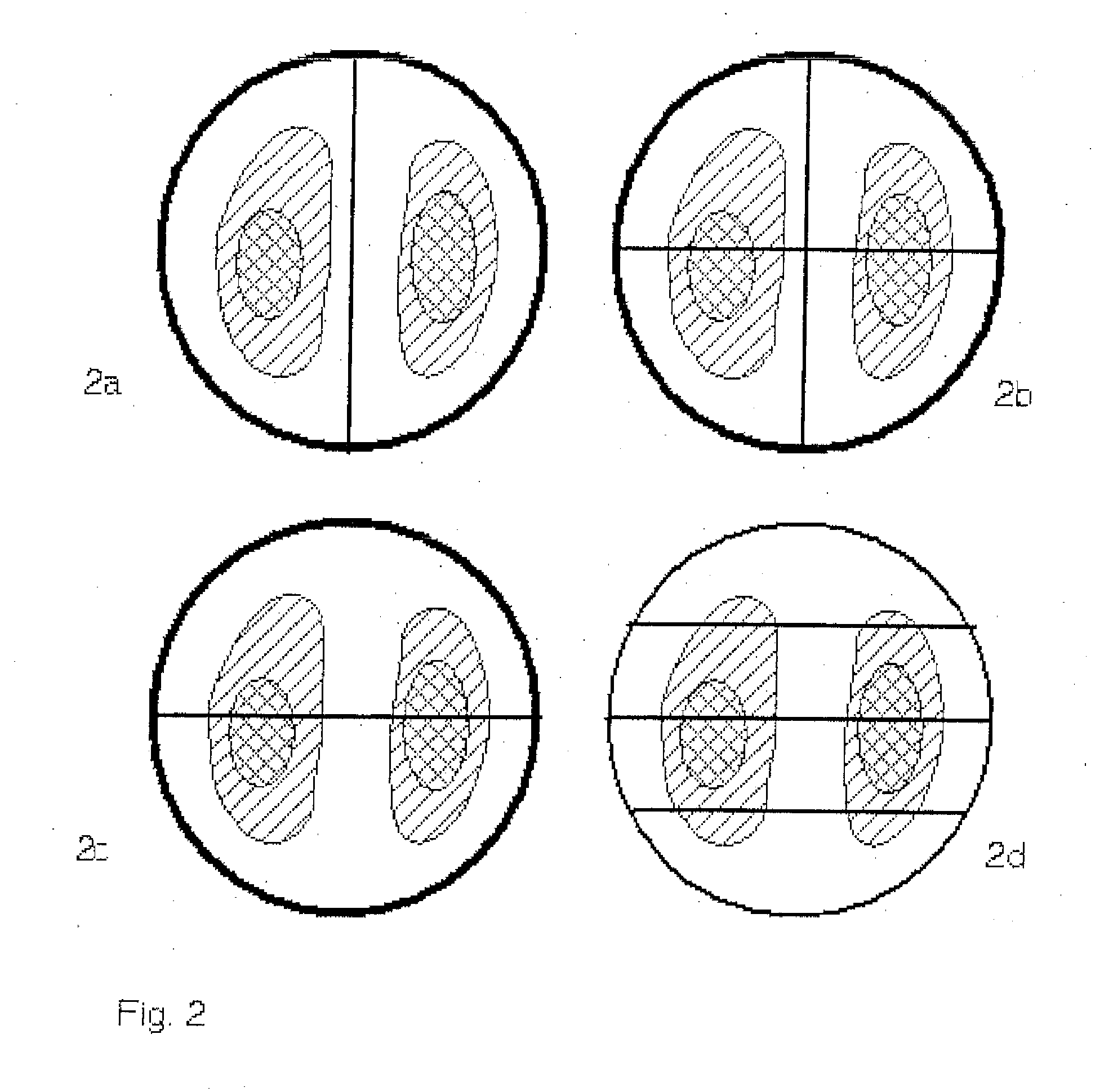
[0025] At least two ranges, within which at least two end-expiratory reference voltages Uref are determined and are used to determine the local change in FRC, are marked during the electroimpedan...


PUM


Abstract

A device and a process for determining the change in the functional residual capacity (FRC) in a simple manner. Based on a first respiration phase for mechanical respiration, a recruitment maneuver is performed for this during a second respiration phase, and respiration is switched back to mechanical respiration during a third respiration phase. Reference values Uref/1, Uref/3 are formed from the end-expiratory values of the impedance measured signals U during the first respiration phase and the third respiration phase, and the difference ΔU (ΔFRC) between the reference value Uref/3 of the third respiration phase and the reference value Uref/1 of the first respiration phase is an indicator of the change in the functional residual capacity of the lung of the test subject.

Description

CROSS REFERENCE TO RELATED APPLICATIONS [0001] This application claims the benefit of priority under 35 U.S.C. § 119 of German Patent Application DE 10 2005 022 896.8 filed May 18, 2005 , the entire contents of which are incorporated herein by reference. FIELD OF THE INVENTION [0002] The present invention pertains to a device and a process for controlling a respirator (ventilator). BACKGROUND OF THE INVENTION [0003] Electroimpedance tomography (EIT) is a method in which a weak electric alternating current is fed into the human body in order to measure the surface potentials at different points of the body. By rotating the points at which the current is fed into the body while measuring the surface potentials at the same time, it is possible to determine a two-dimensional tomogram of the electric impedance distribution in the body being examined by means of suitable mathematical reconstruction algorithms. In medicine, a tomogram of the impedance distribution of the human body is of i...

Claims


Application Information

Patent Timeline
Patent Type & Authority Applications(United States)
IPC IPC(8): A62B7/00
CPCA61B5/0536A61M2230/65A61M16/00A61B5/0809A61M16/024A61B5/085A61B5/091
Inventor GARBER, YVOMATTHIESSEN, HANSWEISMANN, DIETERTESCHNER, ECKHARD
Owner DRAGERWERK AG
Why Eureka
Try Eureka