
Seat structure

a seat structure and seat technology, applied in the direction of chairs, pedestrian/occupant safety arrangements, vehicular safety arrangements, etc., can solve the problems of stiffness of pipes and obstacles, and achieve the effect of improving vibration absorption or appearance, and improving impact force absorption function

Active Publication Date: 2005-07-26
DELTA TOOLING CO LTD
View PDF5 Cites 33 Cited by
  • Summary
  • Abstract
  • Description
  • Claims
  • Application Information

AI Technical Summary

Benefits of technology

[0008]The present invention has been made in consideration of the circumstances described above, and an object of the present invention is to provide a seat structure capable of improving vibration absorbency or appearance when a cushioning layer provided by straining, for instance, a three-dimensional net member (or a two-dimensional net member, a thin urethane material, or the like) as a tension structure is used. Other object of the present invention is to provide a seat structure possible to hold a portion from the waist portion to the haunches of the human body (the pelvis portion) quickly and deeply in the seat back when impact force due to collision etc. is inputted so that the impact force absorbency function can be improved. In order to solve the above-described problem, in the present invention, there is provided a seat structure including a seat back and a seat cushion, and the seat structure is characterized by being composed of:

Problems solved by technology

Besides, the three-dimensional net member provided on the seat back is strained with low tension, which sometimes makes an impression that a slight slack exists in the vicinity corresponding to the waist portion of a seated person, causing a problem in appearance.
However, in the structure disclosed in Patent Document 2, even though the outer pipes are divided into two, since the inner pipes are housed therein, the stiffness of the pipes perform as an obstacle to backward movement of the human body such as sliding into the seat back.

Method used


Image

  • Seat structure
  • Seat structure
  • Seat structure

Examples


Embodiment Construction

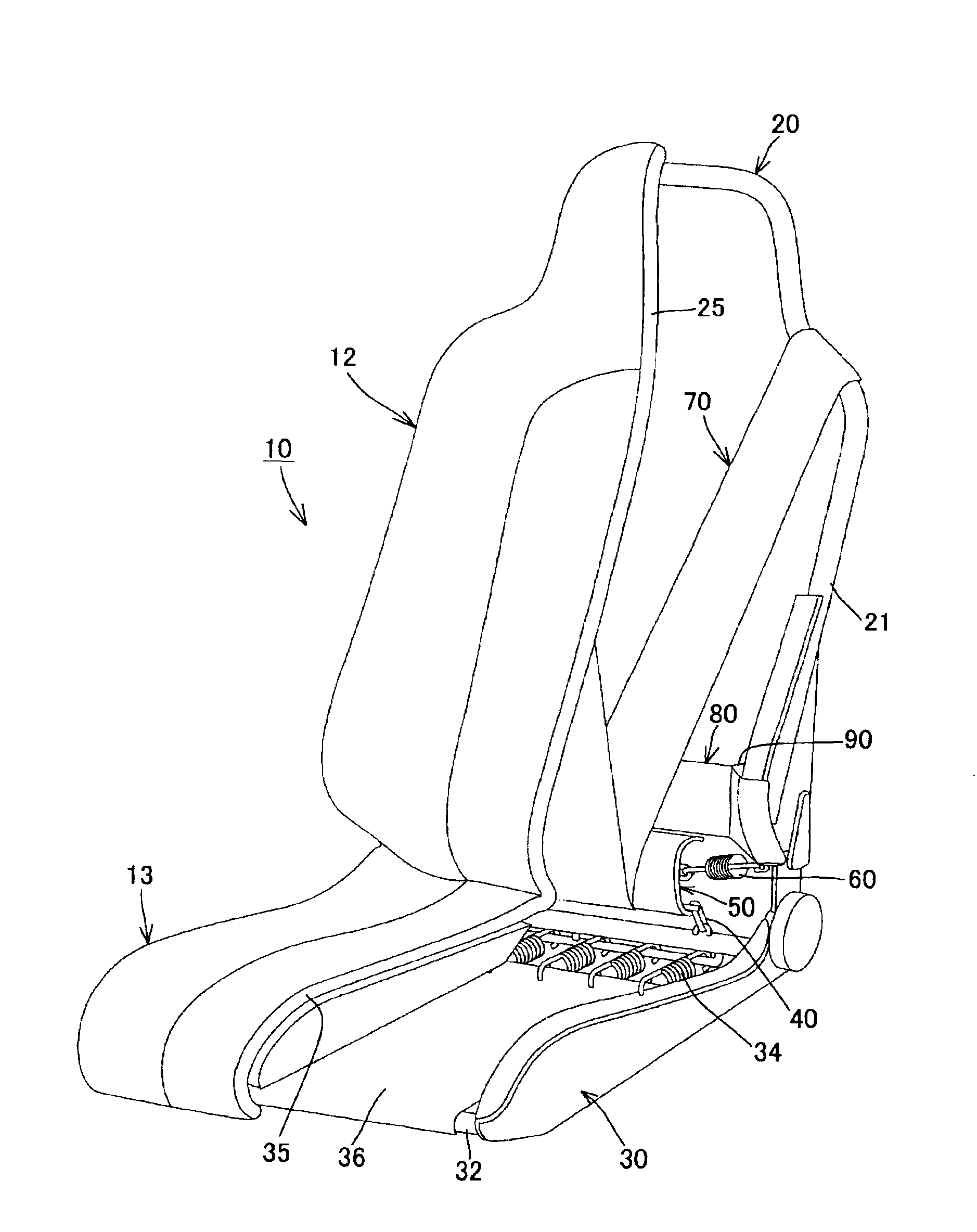
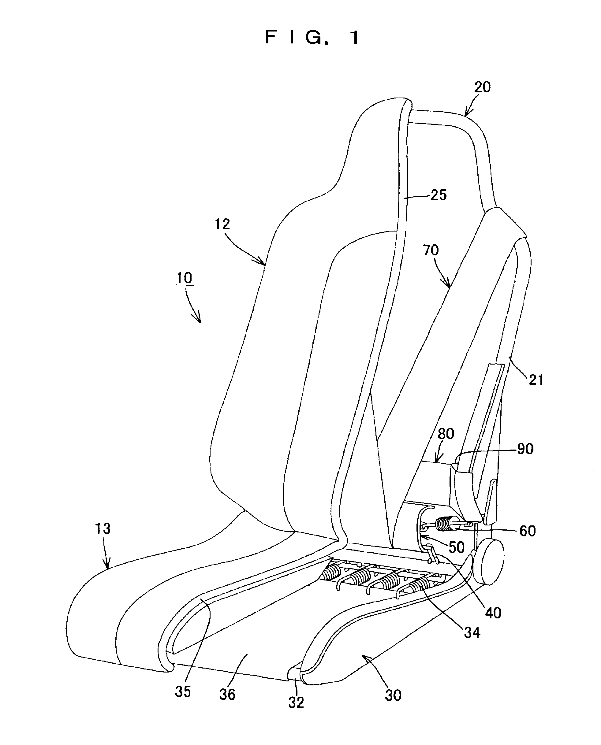
[0031]Hereinafter, the present invention will be explained in more detail based on an embodiment shown in the drawings. FIG. 1 is a diagrammatic perspective view showing a first embodiment of the present invention. As shown in the drawing, a seat structure 10 of the present embodiment is composed of a seat back 12 and a seat cushion 13, the seat back 12 includes a back frame 20 and a cushioning layer 25 strained over the back frame 20 with low tension, and the seat cushion 13 includes a cushion frame 30 and a cushioning layer 35 strained over the cushion frame 30 with low tension.

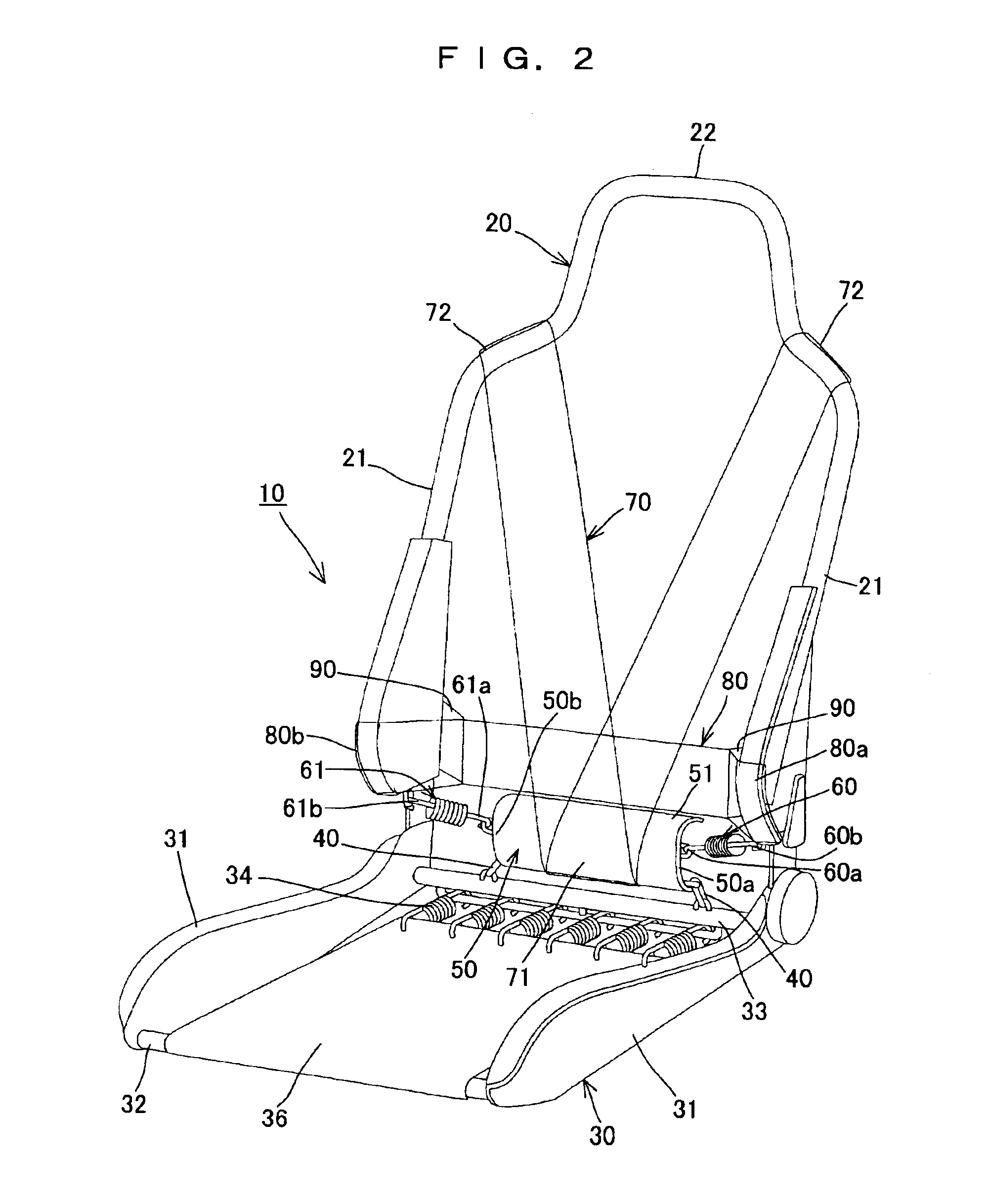
[0032]The back frame 20 is, in more detail, as shown in FIG. 1 and FIG. 2, composed of a pair of side frame members 21 and 21 disposed with a space between them along the width direction of the seat structure 10, and an upper frame member 22. The cushion frame 30 is structured with a pair of side frame members 31 and 31 disposed with an interval in the width direction, a front frame member 32 positioned in ...


PUM


Abstract

In order to improve vibration absorbency and impact absorbency, the seat structure includes a swing member provided in a manner to be able to swing at least back and forth on a rear frame member positioned around the rear of a seat cushion, a pelvis supporting member connected to the swing member at the vicinity of the lower portion of the pelvis supporting member and disposed behind the pelvis of a seated person, and coil springs as an elastic member to support the pelvis supporting member biasing in the direction pushing forwards in a normal seating state. Accordingly, vibration inputted from the seat back side and as if patting on the back of the human body can be absorbed by the pelvis supporting member supported elastically. Besides, since the pelvis supporting member is connected to the rear frame member via the swing member, since pivoting movement in the back-and-forth direction of the pelvis supporting member is performed with a connecting portion of the swing member and the rear frame member as the center, and the radius of gyration is large, the vicinity of the lower portion of the pelvis supporting member never presses the pelvis.

Description

BACKGROUND OF THE INVENTION[0001]1. Field of the Invention[0002]The present invention relates to a seat structure, to be in more detail, a seat structure suitably used for a seat of a transportation equipment such as a plain, a train, a ship, a fork lift and an automobile.[0003]2. Description of the Relevant Art[0004]Patent Document 1 (Japanese Patent Application Laid-open No. 2002-177099) discloses a vehicle seat using a three-dimensional net member (solid knitted fabric) which is excellent in cushioning property even in a thin-type as a cushioning layer, for instance. The cushioning property is served by straining respective cushioning layers made of a three-dimensional net member over a back frame and a cushion frame for forming a seat back and a seat cushion to use as a tension structure.[0005]The vehicle seat disclosed in Patent Document 1 is provided with a sufficient cushioning property even in a thin-type as described above, and excellent air permeability, since it uses a th...

Claims


Application Information

Patent Timeline
IPC IPC(8): B60N2/42B60N2/427B61D33/00A47C7/40B60N2/90
CPCB60N2/42709B61D33/0014B60N2/70B60N2/7011
Inventor FUJITA, ETSUNORISAKAMOTO, YUTAKACHIZUKA, KAZUYOSHIKAWASAKI, SEIJITAKATA, YASUHIDEOGURA, YUMIKANEKO, SHIGEHIKO
Owner DELTA TOOLING CO LTD
Learn More