Circuit breaker trip unit employing a rotary plunger
a circuit breaker and plunger technology, applied in the direction of circuit breaker switches, contact mechanisms, snap-action arrangements, etc., can solve the problems of affecting the trip, affecting the installation and removal of the trip unit, and causing awkward assembly and breakag
- Summary
- Abstract
- Description
- Claims
- Application Information
AI Technical Summary
Benefits of technology
Problems solved by technology
Method used
Image
Examples
Embodiment Construction
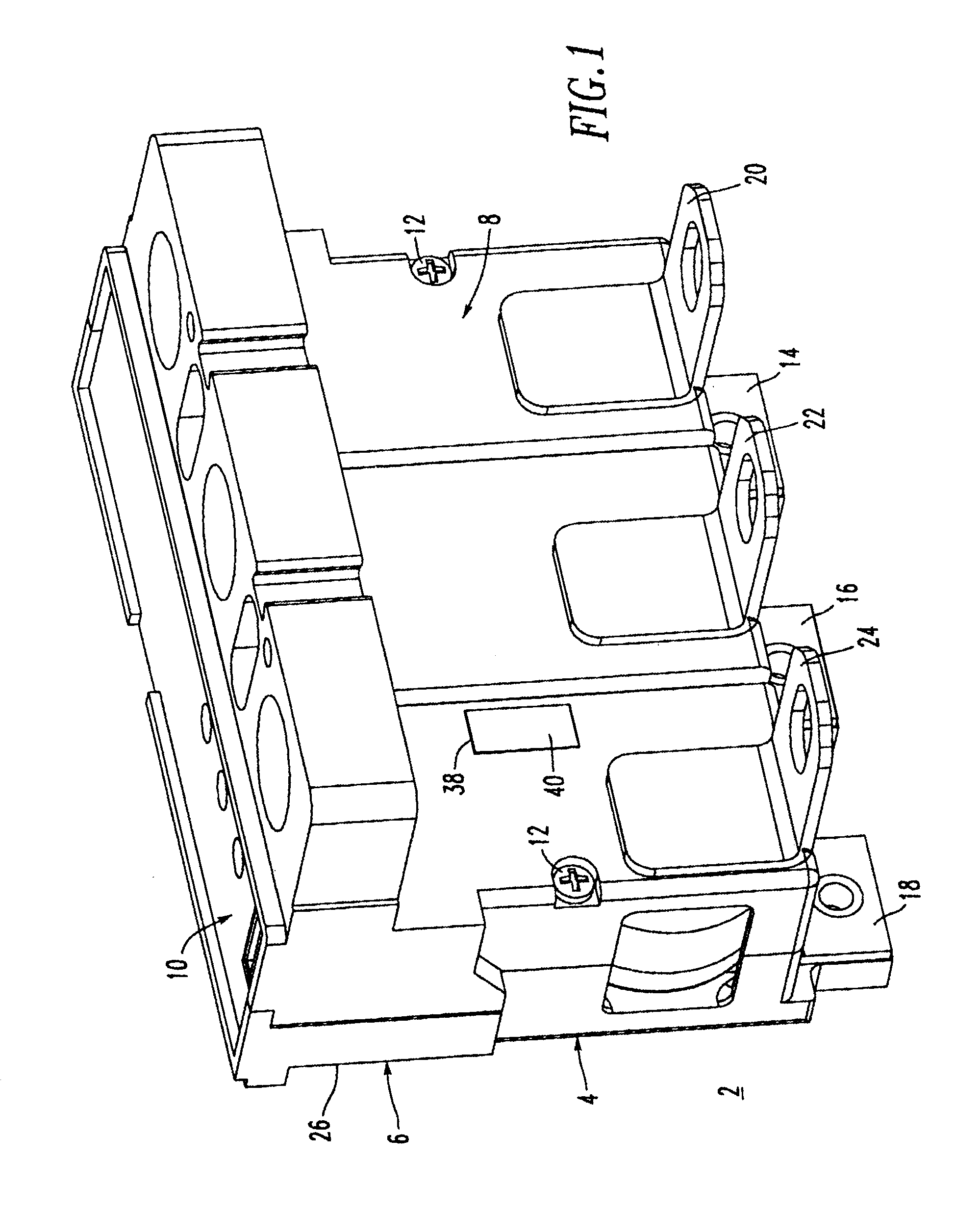
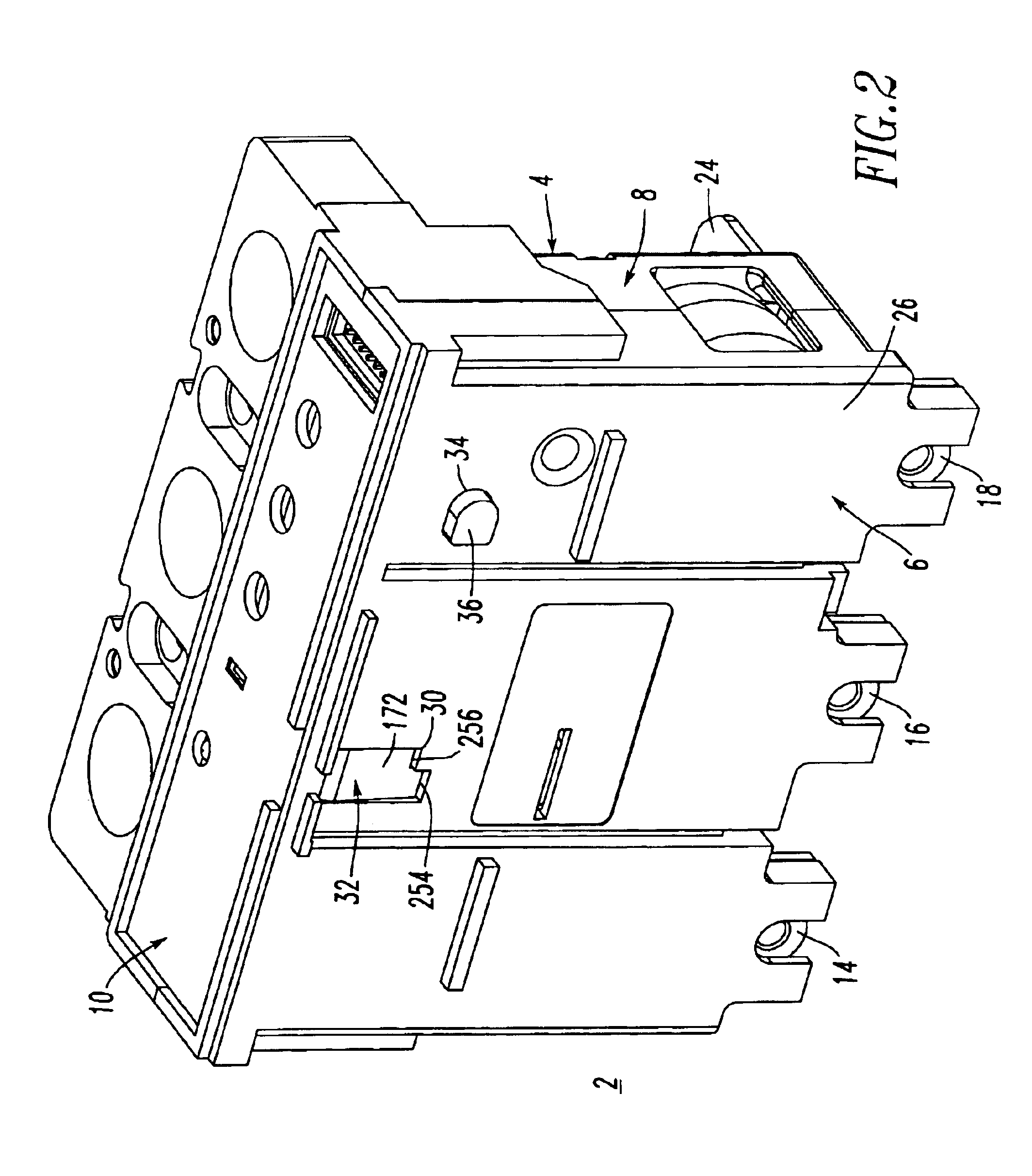
[0045]Referring to FIGS. 1 and 2, a trip unit 2 is shown. The trip unit 2 includes a molded housing 4 having a base 6, a cover 8 and a top portion 10. A pair of screws 12 secures the cover 8 to the base 6. Disposed from the base 6 are three-phase line end terminals 14,16,18. The cover 8 includes corresponding load end terminals 20,22,24, respectively.
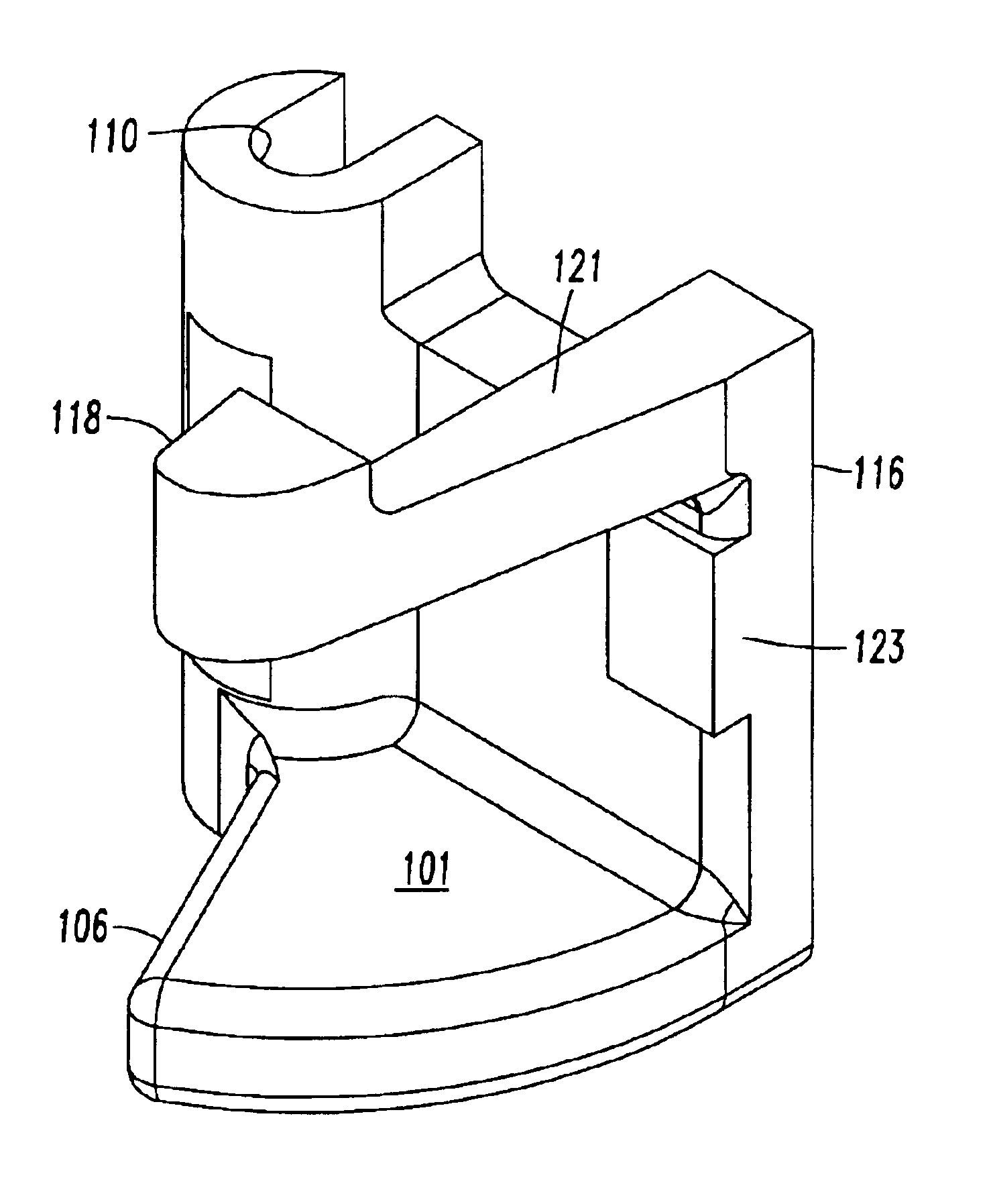
[0046]The base 6 includes a surface 26 (as shown in FIG. 2), which is disposed adjacent to a circuit breaker frame 28 as shown in FIG. 21. The trip unit 2 is advantageously adapted for engagement within and disengagement from the circuit breaker frame 28. The base surface 26 includes an opening 30 for a plunger, such as a rotary plunger 32 (as best shown in FIG. 15), and an opening 34 for an attachment button 36 (as best shown in FIG. 3). As discussed below in connection with FIGS. 4 and 18-20, the rotary plunger 32 is pivotally mounted with respect to the housing 4 and includes a first or on position (FIG. 18), a second or tripped posi...
PUM
 Abstract
Description
Claims
Application Information
 - R&D
- Intellectual Property
- Life Sciences
- Materials
- Tech Scout
- Unparalleled Data Quality
- Higher Quality Content
- 60% Fewer Hallucinations
Browse by: Latest US Patents, China's latest patents, Technical Efficacy Thesaurus, Application Domain, Technology Topic, Popular Technical Reports.
© 2025 PatSnap. All rights reserved.Legal|Privacy policy|Modern Slavery Act Transparency Statement|Sitemap|About US| Contact US: help@patsnap.com


