Display device and method for producing the same

Inactive Publication Date: 2005-07-26
NGK INSULATORS LTD
View PDF29 Cites 4 Cited by
  • Summary
  • Abstract
  • Description
  • Claims
  • Application Information

AI Technical Summary

Benefits of technology

[0026]The present invention has been made in order to solve the problem as described above, an object of which is to provide a display device and a method for producing the same which make it possible

Problems solved by technology

However, even when the deposition heights of the respective precursors and the heat treatment condition are set as described above,

Method used


Image

  • Display device and method for producing the same
  • Display device and method for producing the same
  • Display device and method for producing the same

Examples


Embodiment Construction

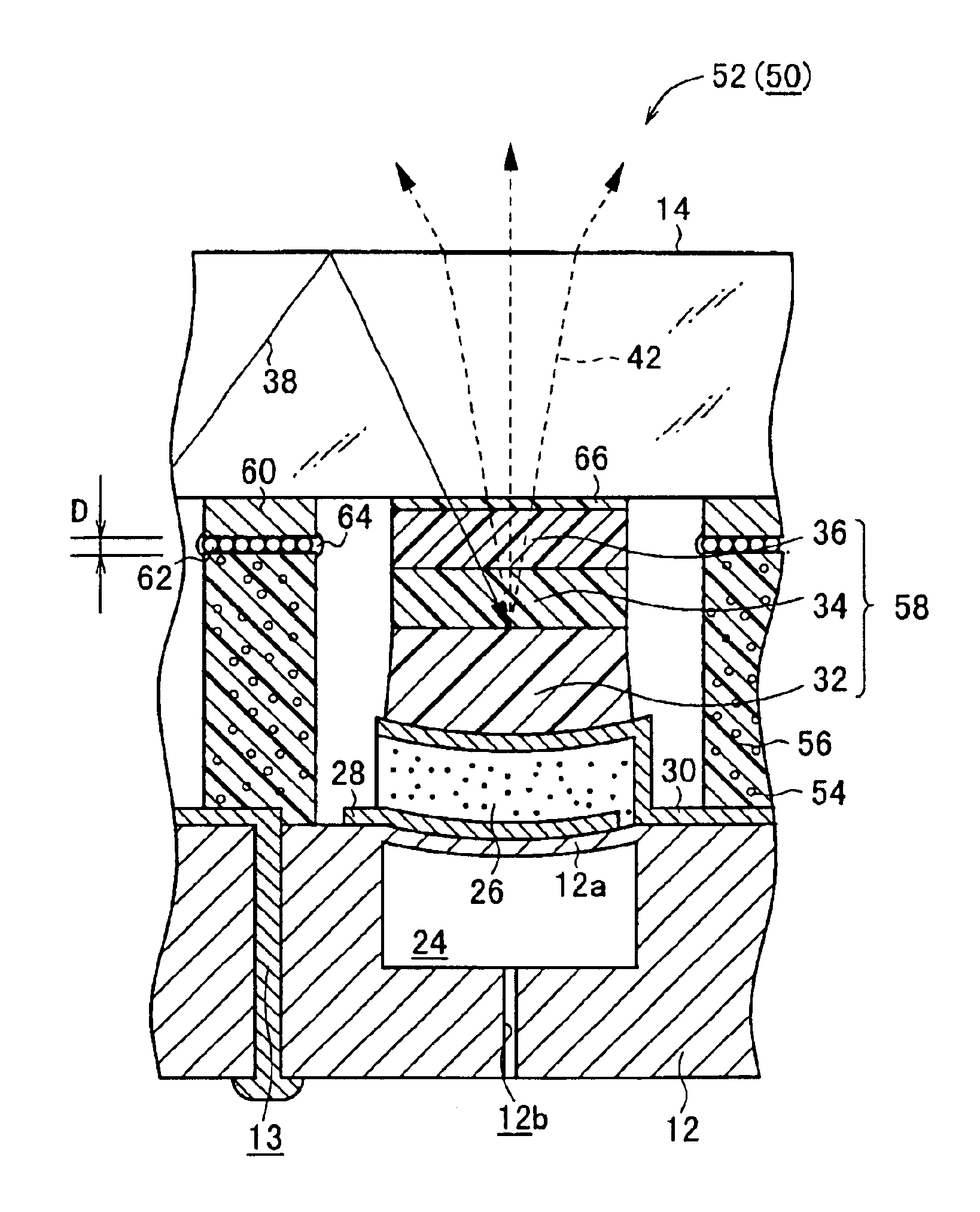
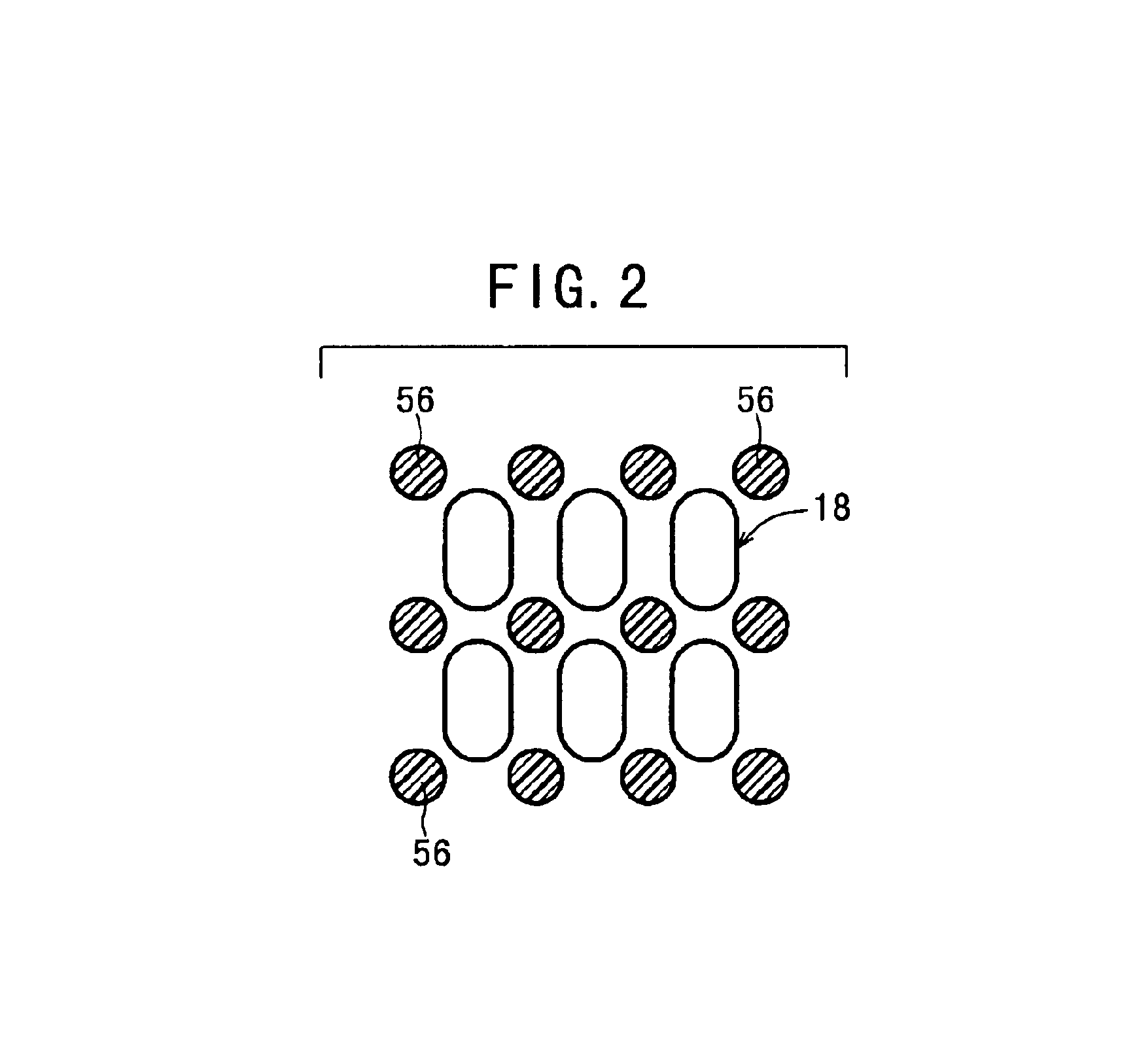
[0097]The display device according to the present invention will be exemplified by preferred embodiments below, which will be explained in detail with reference to the accompanying drawings. Constitutive components corresponding to the constitutive components shown in FIGS. 38 to 41 are designated by the same reference numerals, detailed explanation of which will be omitted.

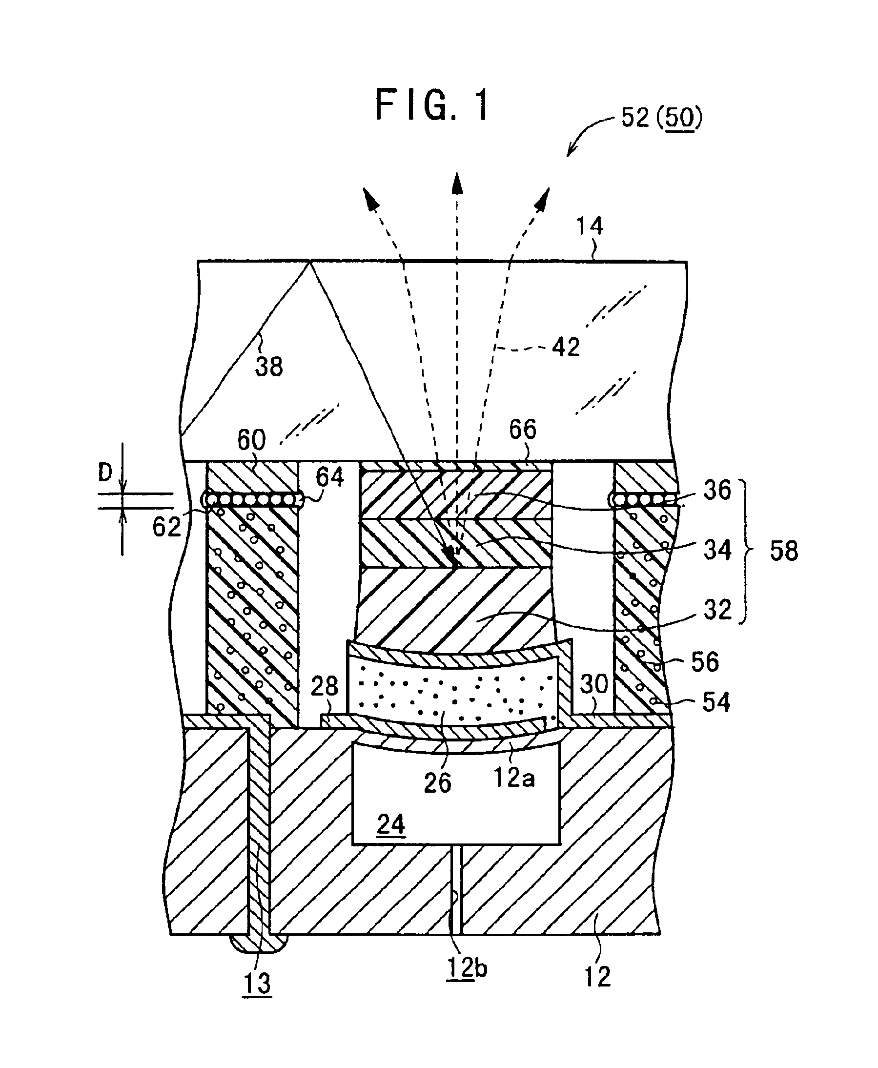
[0098]FIG. 1 shows a schematic sectional view illustrating a unit dot 52 provided for a display device 50 according to an embodiment of the present invention. The display device 50 comprises an actuator substrate 12 which has an actuator element 18 (shown in FIG. 7), an optical waveguide plate 14, and a hardened or cured resin which contains a filler 54. The display device 50 further comprises crosspieces 56 which are allowed to intervene between the actuator substrate 12 and the optical waveguide plate 14, and a picture element assembly 58 which is joined onto the actuator element 18.

[0099]The display device 50 ...


PUM


Abstract

A crosspiece precursor and a picture element assembly precursor are hardened at mutually different timings to form a crosspiece and a picture element assembly. For example, the crosspiece precursor is firstly hardened to form the crosspiece. After that, the picture element assembly precursor is hardened while allowing an upper end surface of the picture element assembly precursor to make pressed contact with an optical waveguide plate, by displacing an actuator element toward an actuator substrate. The picture element assembly, which is formed by hardening the picture element assembly precursor, reliably abuts against the optical waveguide plate when a display device is in a light emission state.

Description

BACKGROUND OF THE INVENTION[0001]1. Field of the Invention[0002]The present invention relates to a display device and a method for producing the same. In particular, the present invention relates to a display device which reliably emits light at a desired luminance, and a method for producing the same.[0003]2. Background of the Invention[0004]FIG. 38 shows an example of a large screen display in which a plurality of display devices are arranged on an optical waveguide plate. The large screen display 100 has, for example, such features that it is of the direct vision type, it is of the thin type, it has a high luminance, and it has a wide angle of visibility. A plurality of display devices 10 as described later on are arranged in the vertical direction and in the lateral direction respectively on a first surface (back surface) of the large optical waveguide plate 102 which is composed of, for example, glass or acrylic to construct the large screen display of the thin type. In additio...

Claims


Application Information

Patent Timeline
IPC IPC(8): G02B26/08
CPCG02B26/08
Inventor TAKEUCHI, YUKIHISANANATAKI, TSUTOMUSHIMOGAWA, NATSUMIAKAO, TAKAYOSHI
Owner NGK INSULATORS LTD
Why Eureka
Try Eureka