Method of producing light emitting apparatus

a technology of light-emitting apparatus and production method, which is applied in the manufacture of electrode systems, electric discharge tubes/lamps, and discharge tubes luminescent screens, etc., can solve the problem of low yield rate of light-emitting apparatus

Inactive Publication Date: 2010-05-04
SHINKO ELECTRIC IND CO LTD
View PDF10 Cites 1 Cited by
  • Summary
  • Abstract
  • Description
  • Claims
  • Application Information

AI Technical Summary

Benefits of technology

[0014]Embodiments of the present invention provide a method of producing a light emitting apparatus that makes it possible to adjust the thickness of a fluorescent-substance-containing resin so that the light emitted from a light emitting apparatus attains the desired luminance and chromaticity.

Problems solved by technology

Also, this difficulty results in a low yield rate of the light emitting apparatus 100.

Method used


Image

  • Method of producing light emitting apparatus
  • Method of producing light emitting apparatus
  • Method of producing light emitting apparatus

Examples


first embodiment

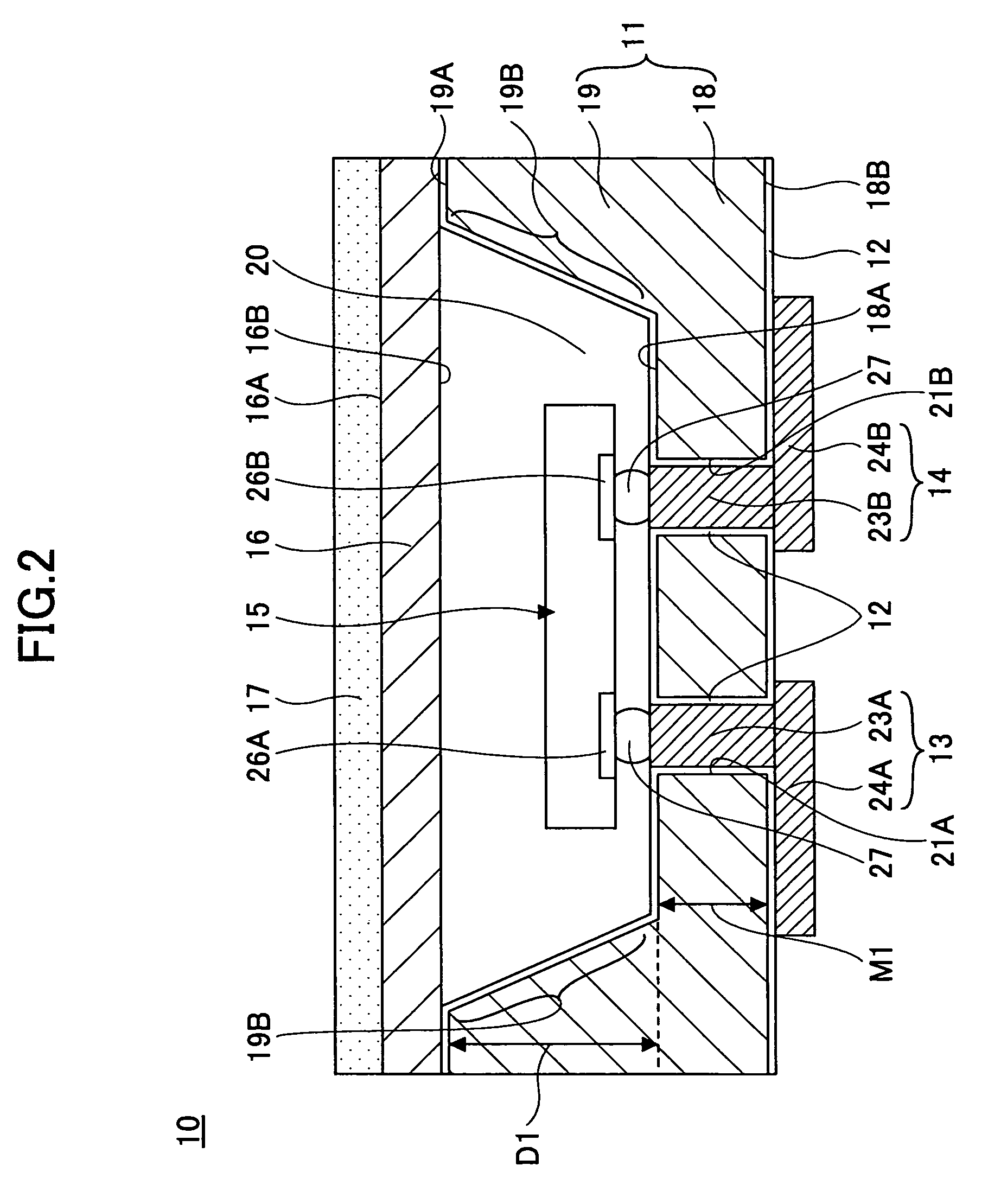
[0038]FIG. 2 is a schematic diagram illustrating an exemplary light emitting apparatus according to a first embodiment of the present invention.

[0039]As shown in FIG. 2, a light emitting apparatus 10 includes a light emitting element housing 11, an insulating film 12, wiring patterns 13 and 14, a light emitting element 15, a translucent substrate 16, and a fluorescent-substance-containing resin 17.

[0040]The light emitting element housing 11 includes a plate part 18, a frame part 19, and a recess 20. The plate part 18 supports the frame part 19 and the plate part 18 and the frame part 19 are formed as a monolithic structure. Through holes 21A and 21B are formed in the plate part 18. A thickness M1 of the plate part 18 is, for example, 200 μm. The frame part 18 is monolithically formed on the plate part 19. An inner wall 19B of the frame part 19 is inclined.

[0041]The recess 20 houses the light emitting element 15 and is formed by an upper surface 18A of the plate part 18 and the inner...

second embodiment

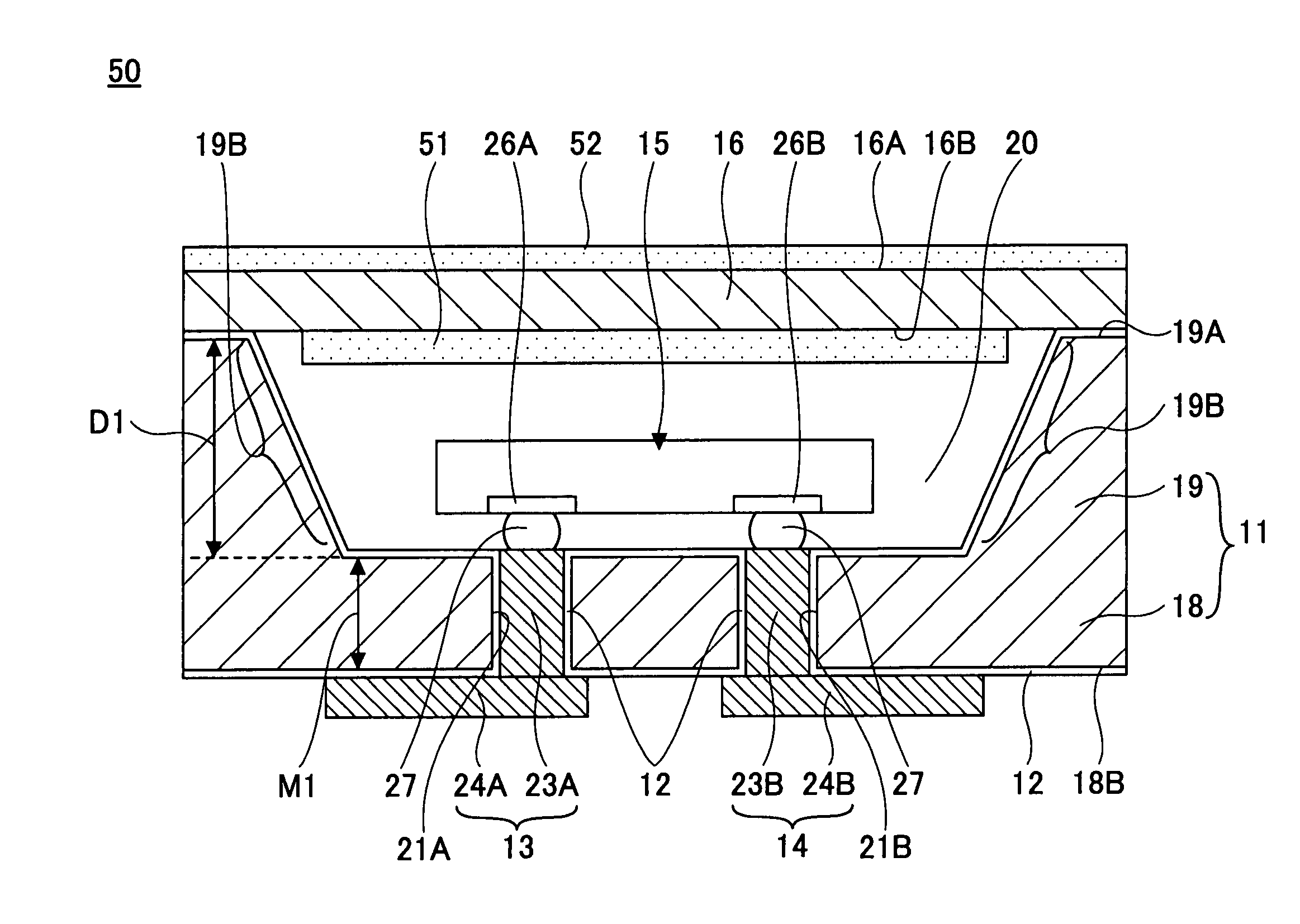
[0073]FIG. 17 is a schematic diagram illustrating an exemplary light emitting apparatus according to a second embodiment of the present invention. In FIG. 17, the same reference numbers are used for the parts corresponding to those of the light emitting apparatus 10 shown in FIG. 2.

[0074]As shown in FIG. 17, a light emitting apparatus 50 according to the second embodiment has substantially the same configuration as that of the light emitting apparatus 10 according to the first embodiment except that a first fluorescent-substance-containing resin 51 and a second fluorescent-substance-containing resin 52 are provided instead of the fluorescent-substance-containing resin 17.

[0075]The first fluorescent-substance-containing resin 51 is formed on the side 16B (the side facing the light emitting element 15 in the recess 20) of the translucent substrate 16. The thickness of the first fluorescent-substance-containing resin 51 is determined to be smaller than a thickness (the sum of the thick...


PUM


Abstract

A method of producing a light emitting apparatus including a light emitting element, a light emitting element housing having a recess for housing the light emitting element, and a translucent substrate placed on the light emitting element housing is disclosed. The disclosed method includes a fluorescent-substance-containing resin forming step of forming a fluorescent-substance-containing resin on a first side of the translucent substrate which first side is opposite to a second side of the translucent substrate which second side faces the recess. In the fluorescent-substance-containing resin forming step, luminance and chromaticity of light that is emitted from the light emitting element and then transmitted by the fluorescent-substance-containing resin are measured and a thickness of the fluorescent-substance-containing resin is adjusted based on the measured luminance and chromaticity so that light emitted from the light emitting apparatus attains the specified luminance and chromaticity.

Description

BACKGROUND OF THE INVENTION[0001]1. Field of the Invention[0002]The present invention generally relates to a method of producing a light emitting apparatus, and more particularly relates to a method of producing a light emitting apparatus which method makes it possible to adjust the luminance and chromaticity of light emitted from the light emitting apparatus.[0003]2. Description of the Related Art[0004]FIG. 1 is a schematic diagram illustrating a conventional light emitting apparatus.[0005]As shown in FIG. 1, a light emitting apparatus 100 includes a light emitting element housing 101, through-vias (plugs) 102, a light emitting element 103, a translucent substrate 106, and a fluorescent-substance-containing resin 107.[0006]In the light emitting element housing 101, a recess 108 for housing the light emitting element 103 and through holes 109 are formed. The through-vias 102 are formed in the through holes 109 of the light emitting element housing 101. The light emitting element 103...

Claims


Application Information

Patent Timeline
Patent Type & Authority Patents(United States)
IPC IPC(8): H01J1/62H01L33/62H01L33/50
CPCH01L33/507H01L2933/0041H01L24/97H01L2224/16225H01L2924/16195H01L2224/97
Inventor TAGUCHI, YUICHISUNOHARA, MASAHIROSAKAGUCHI, HIDEAKISHIRAISHI, AKINORIKOIZUMI, NAOYUKIMURAYAMA, KEIHIGASHI, MITSUTOSHI
Owner SHINKO ELECTRIC IND CO LTD
Why Eureka
Try Eureka