
Illumination control device

Active Publication Date: 2017-08-08
YAZAKI CORP
View PDF17 Cites 0 Cited by
  • Summary
  • Abstract
  • Description
  • Claims
  • Application Information

AI Technical Summary

Benefits of technology

The invention is an illumination control device that allows for easy control of the color of light emitted from various light sources. This device can calibrate correction coefficients to achieve the desired color, even if the light source has changed over time or has large variations in its light emission characteristics. The device can also control the light source to a specific reference state, making it easy to detect any differences in chromaticity between different light sources. Overall, this device expands the options for light sources and reduces the cost of the illumination system.

Problems solved by technology

Therefore, when the full-color LED device is used as a light source of an illumination device for illuminating a cabin, there is a case in which illumination light with desired chromaticity estimated at design cannot be obtained.
However, since there is a large variation in light-emitting characteristic due to individual differences among the LED devices, hue of illumination perceived by a user may differ from one place to another in the cabin.
Accordingly, special LED devices which have been selected beforehand must be used so that individual differences among the LED devices in actual use can be limited to be small.
Accordingly, component cost of each LED device to be used inevitably increases greatly in comparison with an ordinary LED device.

Method used


Image

  • Illumination control device
  • Illumination control device
  • Illumination control device

Examples


first embodiment

(First Embodiment)

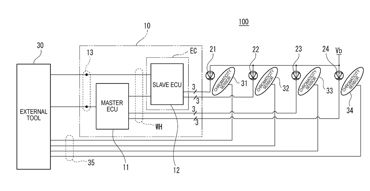
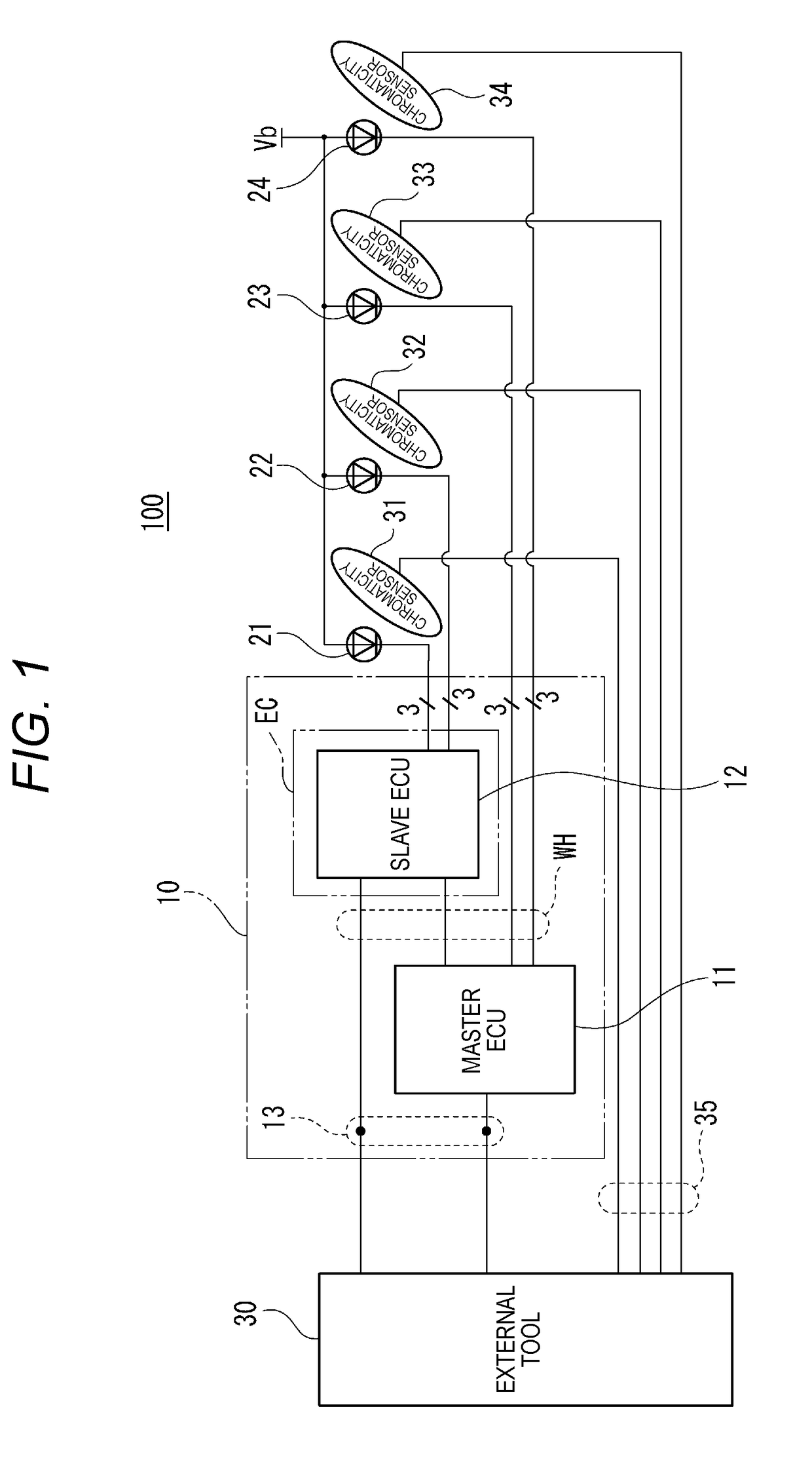
[0034]A configuration example (1) of a calibration system 100 for a vehicle, which includes an illumination control device according to an embodiment of the invention, is shown in FIG. 1. The calibration system 100 shown in FIG. 1 is provided with an illumination control device 10, an external tool 30, LED devices 21 to 24, and chromaticity sensors 31 to 34.

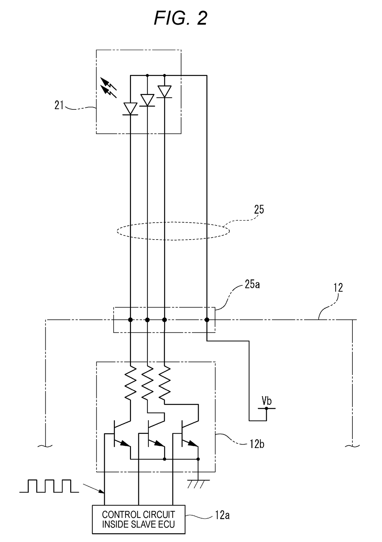
[0035]The LED devices 21 to 24 serve as light sources respectively for illuminating a cabin of the vehicle. Specifically, each of the LED devices 21 to 24 uses a full-color LED containing three LED (Light-Emitting Diode) elements emitting lights at R (Red), G (Green) and B (Blue) color wavelengths respectively. These LED devices 21 to 24 are disposed at different places in the cabin respectively so that various places in the cabin can be illuminated by the LED devices 21 to 24 with proper light quantities and proper chromaticities.

[0036]The illumination control device 10 is a device for controlling the illuminat...

second embodiment

(Second Embodiment)

[0071]A configuration example (2) of a calibration system 100B for a vehicle, which includes an illumination control device according to an embodiment of the invention, is shown in FIG. 6. The calibration system 100B shown in FIG. 6 includes an illumination control device 10B, a meter ECU 40, and LED devices 21 to 24.

[0072]The meter ECU 40 is an electronic control unit which is built in a meter unit providing a function of an instrument panel on the vehicle. In the embodiment, the meter ECU 40 accepts a user's input operation for performing calibrating work on the illumination control device 10B. Incidentally, when change is made to allow the master ECU 11 inside the illumination control device 10B to execute control of the meter ECU 40, use of the meter ECU 40 becomes unnecessary.

[0073]In the same manner as that in the first embodiment, each of the LED devices 21 to 24 shown in FIG. 6 is a light source for illuminating a cabin of the vehicle. Specifically, each o...


PUM


Abstract

An illumination control device includes a control portion which controls light emission states of luminous bodies and having different light emission colors from one another, so that a cabin is illuminated by emitted light emitted from a light source and having predetermined chromaticity. The light source has the luminous bodies. The control portion controls the light emission states of the luminous bodies in accordance with a correction coefficient inputted from outside to adjust the chromaticity of the emitted light.

Description

CROSS REFERENCE TO RELATED APPLICATIONS[0001]This application is based on Japanese Patent Application (No. 2015-211039) filed on Oct. 27, 2015, the contents of which are incorporated herein by reference.BACKGROUND OF THE INVENTION[0002]1. Field of the Invention[0003]The present invention relates to an illumination control device which can be used for illumination of a vehicle etc.[0004]2. Description of the Related Art[0005]For example, it is assume that a cabin is illuminated in a vehicle such as a passenger vehicle. In this case, it is desired that the cabin is illuminated by illumination light with proper chromaticity in accordance with the state at that time. In such an application, for example, a full-color LED device containing a plurality of light-emitting elements (LEDs: Light-Emitting Diodes) emitting lights at red (R), green (G) and blue (B) color wavelengths respectively is used as a light source. Thus, it is possible to obtain illumination light with various chromaticiti...

Claims


Application Information

Patent Timeline
IPC IPC(8): H05B33/08H05B37/02B60Q3/80H05B44/00
CPCH05B33/0866B60Q3/80H05B37/0227H05B45/00H05B45/50H05B45/24H05B45/46H05B47/105H05B45/20H05B47/11Y02B20/40
Inventor OHASHI, TOMONORISUGIMOTO, TERUMITSUBARASAWA, HIROKOSUZUKI, YASUO
Owner YAZAKI CORP
Learn More