
Lighting device with flipped side-structure of LEDs

Inactive Publication Date: 2006-10-05
IND TECH RES INST
View PDF9 Cites 11 Cited by
  • Summary
  • Abstract
  • Description
  • Claims
  • Application Information

AI Technical Summary

Benefits of technology

[0008] The present invention has been made to overcome the drawbacks of conventional light sources. It eliminates the need of a conventional wire bonding process and a package for encasing an LED chip, and thus reduces cost and space. A high light intensity with desired chromaticity is also achieved due to a high LED packaging density and a proper mix of the emitted lights.
[0014] The present invention achieves good uniformity and high intensity of the combined lights with desired chromaticity.

Problems solved by technology

However, most commercially available LEDs are made with a limited number of chromaticity choices and their chromaticity may change over time.
However, all these schemes increase the complexity and cost of the light source.
Therefore, there is a limited flexibility for chromaticity adjustment.
The side-emitter may provide good uniformity of combined light but the light intensity is poor.
The disadvantage of this LED structure is poor light intensity because the non-transparent metal pads 501 and 502 block a significant portion of the emitted lights.
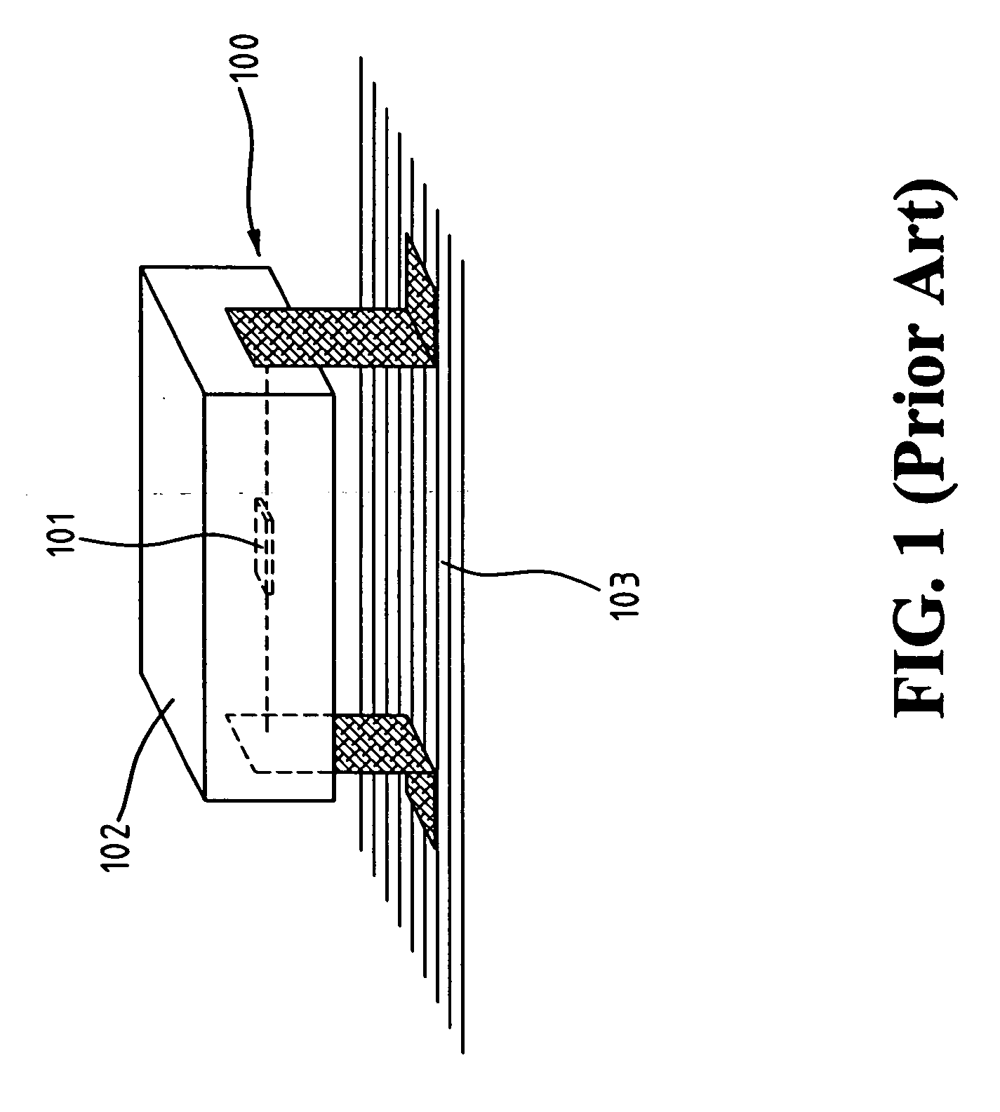
Moreover, the requirement of a conventional wire bonding process increases its process complexity, package size, and cost

Method used


Image

  • Lighting device with flipped side-structure of LEDs
  • Lighting device with flipped side-structure of LEDs
  • Lighting device with flipped side-structure of LEDs

Examples


first embodiment

[0037]FIG. 7B shows a top view of the lighting device with flipped side-structure of LEDs according to the present invention. Without loss of generality, a plurality of the n-electrode pads and p-electrode pads can be patterned such that an array of LEDs are connected together in a serial manner and / or in a parallel manner. The packaging structure of the present invention also resolves the heat dissipation problem of the LED device.

[0038] With the lighting device with flipped side-structure of LEDs, the emitted lights can travel in parallel with a mounting surface. It eliminates the need of a conventional wire bonding process and a package for encasing an LED chip, and thus reduces cost and space. The lighting device with flipped side-structure of LEDs can be further combined with optical protrusions on the substrate to form a light module for reflecting and mixing lights emitted from the LED chips to meet desired applications. A high light intensity with desired chromaticity is als...

third embodiment

[0045] The lighting device of the present invention can be incorporated in a light source, such as an LED lamp. FIGS. 12A and 12B are application examples of an LED lamp without or with a reflective bowl according to the present invention.

[0046] Referring to application examples shown in FIGS. 9, 11, and 12A, the lighting devices are formed on a substrate facing the optical protrusions to form an LED luminance sources. Therefore, the emitted lights from different LEDs have a chance to be reflected and combined near the substrate surface in order to achieve desired chromaticity. FIG. 12B is an application example of FIG. 12A combined with a reflective bowl 1201. FIG. 12C is a front view of the LED lamp with a reflective bowl shown in FIG. 12B.

[0047] The present invention achieves good uniformity and high intensity of the combined lights with desired chromaticity. The combined lights emitted from the light module can be further directed towards a light diffuser or a wave guide. The l...


PUM


Abstract

Disclosed is a lighting device with flipped side-structure of LEDs, which allows emitted lights to travel in parallel with the mounting surface. Single or plural LED chips are mounted on a substrate with their side surfaces facing the substrate surface. The lighting device can be further combined with optical protrusions on the substrate to form a light module for reflecting and mixing lights emitted from the LED chips. It does not require a conventional wire bonding process. The packaging structure also resolves the heat dissipation problem of the LEDs. Electrostatic discharge protection circuits can be included in the light module if desired. The invention achieves good uniformity and high intensity of the combined lights with desired chromaticity.

Description

FIELD OF THE INVENTION [0001] The present invention generally relates to light emitting diode (LED) devices, and more specifically to a lighting device with flipped side-structure of LEDs. BACKGROUND OF THE INVENTION [0002] A light source for illuminating an information source is often required in many applications. In particular, liquid crystal displays (LCDs) have become more and more popular in many electronic media LCDs are commonly adopted in various applications, such as laptop computers, display monitors, video cameras, automatic teller machine displays, displays in avionics, televisions etc. In general, a backlight module is required for the LCDs to illuminate the information to be displayed. There are various kinds of light sources used in a backlight module of an LCD, e.g., fluorescent lamps and LEDs. While the fluorescent lamps are inexpensive and do not need complex control circuitry. They are sometimes inadequate for certain applications that require good color quality ...

Claims


Application Information

Patent Timeline
IPC IPC(8): H01L33/00F21K99/00
CPCF21K9/00H01L2924/181H01L2224/48091H01L2224/48227F21Y2115/10F21Y2107/30H01L2224/45144H01L2924/00012H01L2924/00014H01L2924/00
Inventor TAIN, RA-MINLIAU, SHYI-CHINGYANG, CHIEN-CHENG
Owner IND TECH RES INST
Learn More