Illumination device and liquid crystal display device provided therewith
- Summary
- Abstract
- Description
- Claims
- Application Information
AI Technical Summary
Benefits of technology
Problems solved by technology
Method used
Image
Examples
first preferred embodiment
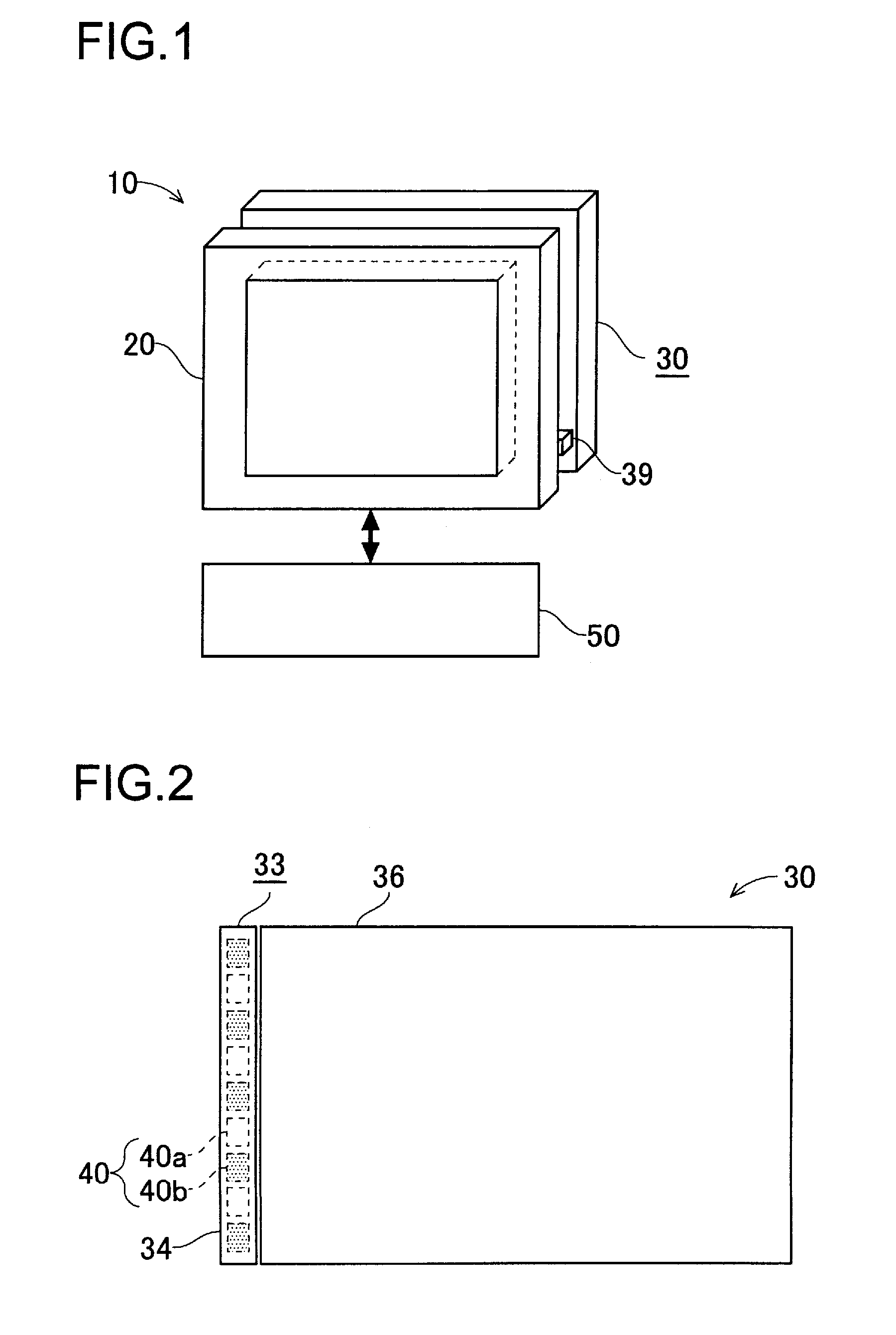
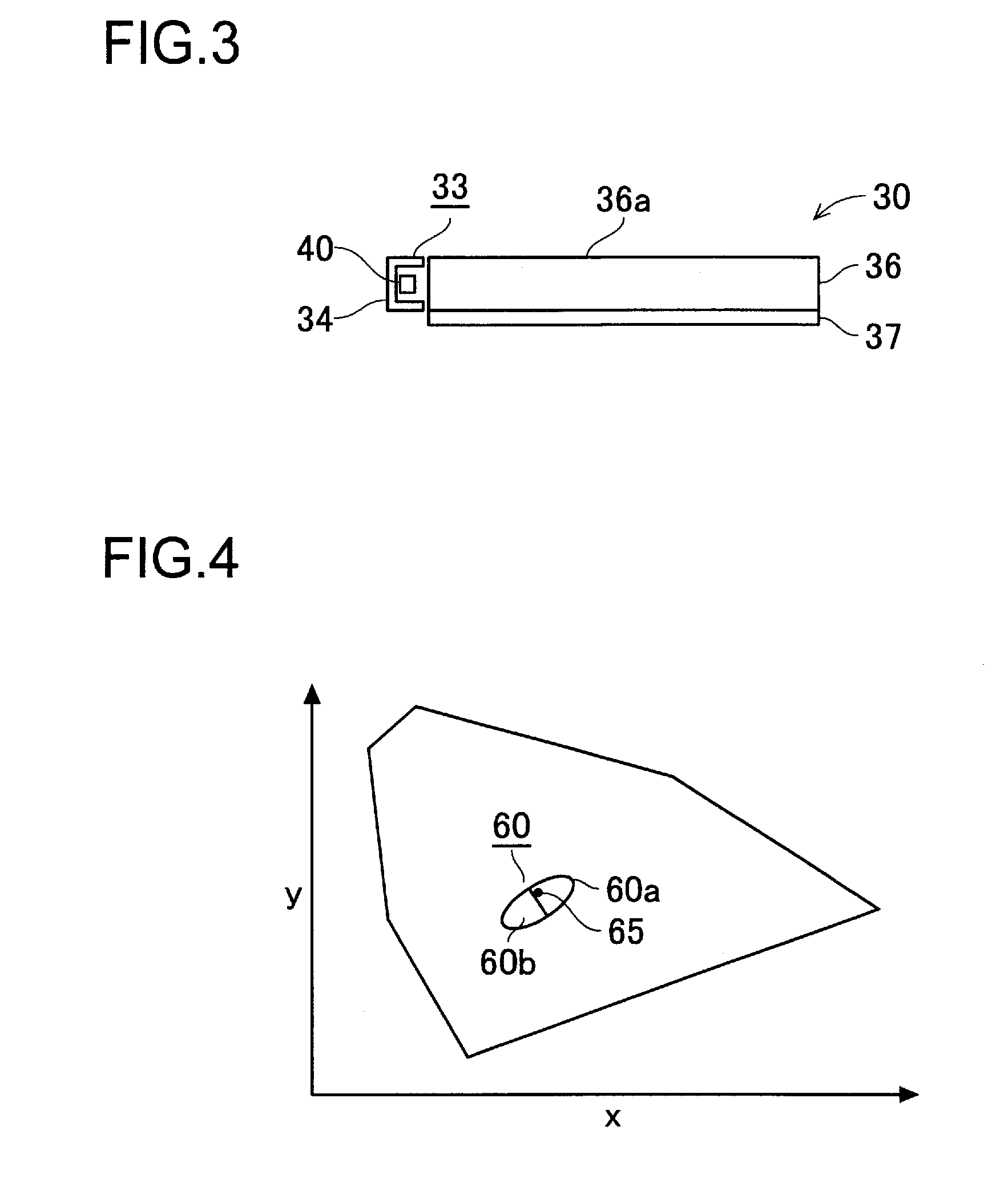
[0028]A first preferred embodiment of the present invention will be described with reference to the accompanying drawings. FIG. 1 is a diagram schematically showing the configuration of a liquid crystal display device according to the first preferred embodiment of the invention. FIG. 2 is a plan view of a backlight according to the first preferred embodiment of the invention. FIG. 3 is a front view of the backlight according to the first preferred embodiment of the invention.
[0029]As shown in FIG. 1, the liquid crystal display device 10 has a liquid crystal panel 20, the backlight 30 serving as an illumination device and a control device 50. The liquid crystal panel 20 has a TFT substrate, an opposite substrate and liquid crystal sealed in therebetween; the orientation of the liquid crystal is controlled by applying voltage to both the substrates based on signals from the control device 50, and this allows an image to be displayed. The backlight 30 is disposed on the back of the liq...
second preferred embodiment
[0040]A second preferred embodiment of the present invention will be described with reference to the accompanying drawings. FIG. 7 is a plan view of a backlight according to the second preferred embodiment. The second preferred embodiment is the same as the first preferred embodiment except that the configuration of the backlight is different from each other, and such parts as are substantially the same as each other are identified with common reference numerals.
[0041]As shown in FIG. 7, the backlight 30 of the second preferred embodiment has a substrate 32 on which white LEDs 40 are mounted, and the backlight 30 is a direct-type backlight. As shown in FIG. 1, the backlight 30 is disposed on the back of the liquid crystal panel 20. The substrate 32 is substantially as large as the liquid crystal panel 20. The white LEDs 40 are arranged on the substrate 32 vertically and horizontally, in a plane.
[0042]In this preferred embodiment, as in the first preferred embodiment, the white LED 4...
third preferred embodiment
[0050]A third preferred embodiment of the present invention will be described with reference to the accompanying drawings. FIG. 10 is a diagram schematically showing the configuration of a white LED according to the third preferred embodiment. The third preferred embodiment is the same as the first and second preferred embodiments except that the configuration of the white LED is different from each other.
[0051]As shown in FIG. 10, the white LED 40 of this preferred embodiment has a frame 42 formed of white resin (the frame 42 is filled with transparent resin), two pairs of lead frames 43, terminals 44 connected to the lead frames 43 and two LED chips 41. Inside the frame 42, the LED chips 41 are connected with wires 45 to the lead frames 43 located on the right and left sides of the figure. The LED chips 41 emit white light; they are formed by, for example, sealing an LED element emitting blue light when being energized with resin containing fluorescent material that emits, when re...
PUM
 Abstract
Description
Claims
Application Information
 - R&D
- Intellectual Property
- Life Sciences
- Materials
- Tech Scout
- Unparalleled Data Quality
- Higher Quality Content
- 60% Fewer Hallucinations
Browse by: Latest US Patents, China's latest patents, Technical Efficacy Thesaurus, Application Domain, Technology Topic, Popular Technical Reports.
© 2025 PatSnap. All rights reserved.Legal|Privacy policy|Modern Slavery Act Transparency Statement|Sitemap|About US| Contact US: help@patsnap.com


