Display device and method that divides one frame period into a plurality of subframe periods and that displays screens of different colors in accordance with the subframe periods

a display device and subframe period technology, applied in static indicating devices, non-linear optics, instruments, etc., can solve the problems of low light use efficiency of liquid crystal display devices adopting color filter methods, liquid crystal display devices adopting field sequential methods, and are attracting attention, so as to achieve desired luminance, reduce the effect of mixing colors and shorten the transmittan

Active Publication Date: 2016-03-08
SHARP KK
View PDF15 Cites 0 Cited by
  • Summary
  • Abstract
  • Description
  • Claims
  • Application Information

AI Technical Summary

Benefits of technology

[0037]According to the first aspect of the present invention, in display of each color, by configuring the second delay time, a period (additional on period) is provided for which the light sources of each color remain turned on until the second delay time has elapsed since the end timing of a subframe period. Therefore, by providing the additional on period, it is possible to secure a longer period in which display is performed in a state close to desired transmittance. In other words, luminance close to a desired value can be achieved for each color. In addition, since the second delay time relating to the light sources for which the off state begins in the preceding subframe period is configured in such a way as to be shorter than the first delay time relating to the light sources for which the on state begins in the succeeding subframe period, a period (all-off period) in which the light sources of all the colors are in the off state is provided. As a result, a period in which the light sources remain turned on while the transmittance is changing becomes shorter. In other words, a period in which the light sources remain turned on while the transmittance is not changing or is not substantially changing becomes relatively long. At this time, the on periods of the light sources can be configured independently of timings at which the subframe period switches. Thus, since a period in which a color corresponding to transmittance and the color of the light sources do not match becomes shorter, mixing of colors can be suppressed. As described above, by providing both the all-off period and the additional on period, desired luminance can be achieved while suppressing mixing of colors.
[0038]According to the second aspect of the present invention, since the first delay time and the second delay time are variable, the luminance of the screen can be changed as necessary. As a result, more desirable luminance can be achieved.
[0039]According to the third aspect of the present invention, since the on periods of the light sources of the plurality of colors can be different from one another, the value of luminance of each color can be adjusted. Therefore, for example, color balance can be improved.
[0040]According to the fourth aspect, the lengths of the on periods of the light sources of the plurality of colors can become the same, and the lengths of these on periods can be variable. Therefore, for example, the luminance of the screen can be changed as necessary. As a result, more desirable luminance can be achieved.
[0041]According to the fifth aspect of the present invention, the same advantageous effects produced by the first aspect of the present invention can be produced through a simple process by using the first delay time and the second delay time fixed for each color.
[0042]According to the sixth aspect of the present invention, the light sources are controlled using the first delay time and the second delay time configured such that the color temperature of the white luminance displayed by the display unit becomes the certain value. Therefore, luminance closer to a desired value can be achieved.

Problems solved by technology

Because, however, about two-thirds of backlight radiated onto a liquid crystal display panel is absorbed by the color filters, there is a problem in that the light use efficiency of a liquid crystal display device adopting a color filter method is low.
Therefore, liquid crystal display devices adopting a field sequential method, which perform color display without using color filters, are attracting attention.

Method used


Image

  • Display device and method that divides one frame period into a plurality of subframe periods and that displays screens of different colors in accordance with the subframe periods
  • Display device and method that divides one frame period into a plurality of subframe periods and that displays screens of different colors in accordance with the subframe periods
  • Display device and method that divides one frame period into a plurality of subframe periods and that displays screens of different colors in accordance with the subframe periods

Examples


first embodiment

[0053]

[0054]

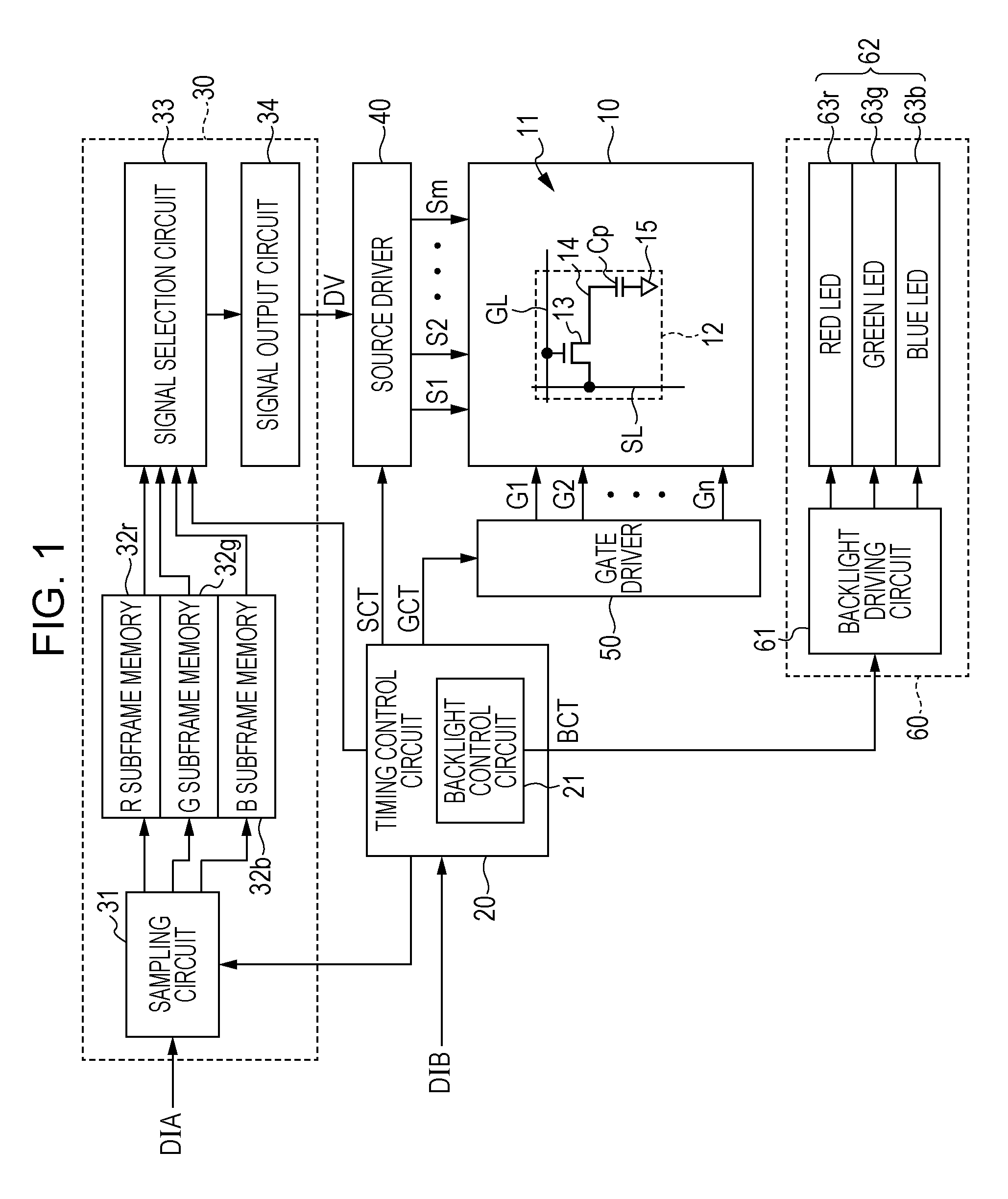
[0055]FIG. 1 is a block diagram illustrating the configuration of a liquid crystal display device adopting a field sequential method according to the first embodiment of the present invention. The liquid crystal display device according to this embodiment performs color display using a field sequential method in which each frame period is divided into three subframe periods. As illustrated in FIG. 1, this liquid crystal display device is configured by a liquid crystal display panel 10, a timing control circuit 20, a subframe image signal generation circuit 30, a source driver 40, a gate driver 50, and a backlight unit 60.

[0056]In the following description, for example, one frame period lasts 1 / 60 second, and each subframe period lasts 1 / 180 second. In addition, assume that a red component (R component), a green component (G component), and a blue component (B component) of an input image signal DIA input to the liquid crystal display device from the outside are each 8-bi...

second embodiment

[0078]

[0079]

[0080]FIG. 4 is a diagram illustrating the operation of a liquid crystal display device according to the second embodiment of the present invention. It is to be noted that this embodiment is the same as the first embodiment except for the configuration of the lengths of the on periods, and accordingly description of the same elements is omitted. In the first embodiment, the R on period, the G on period, and the B on period are uniformly configured in such a way as to have the same length and the lengths of these on periods are a fixed value. In contrast, whereas the R on period, the G on period, and the B on period in this embodiment are uniformly configured in such a way as to have the same length, the lengths of these on periods are variable. In addition, the driving current value of the LEDs 63 of each color may be changed as necessary in accordance with a change in the length of each on period.

[0081]A method for changing the length of each on period is not particular...

third embodiment

[0084]

[0085]

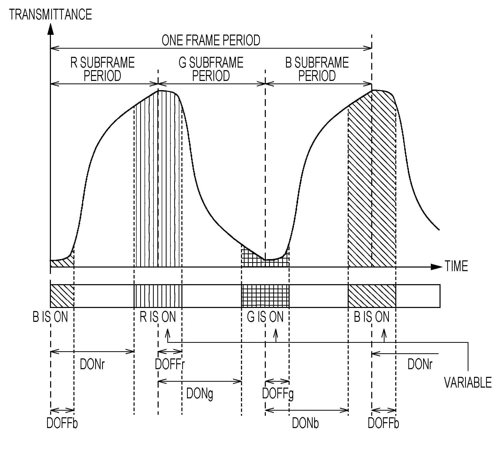
[0086]FIG. 5 is a diagram illustrating the operation of a liquid crystal display device according to the third embodiment of the present invention. It is to be noted that this embodiment is the same as the first or second embodiment except for the configuration of the lengths of the on periods, and accordingly description of the same elements is omitted. In the second embodiment, the R on period, the G on period, and the B on period are uniformly configured in such a way as to have the same length, and the lengths of these on periods are variable. In contrast, the R on period, the G on period, and the B on period in this embodiment can have different lengths. In addition, as in the second embodiment, the driving current value of the LEDs 63 of each color may be changed as necessary in accordance with a change in the length of each on period.

[0087]In the first and second embodiments, the lengths of the R on period, the G on period, and the B on period are the same, and, f...


PUM

PropertyMeasurementUnit
color temperatureaaaaaaaaaa
colorsaaaaaaaaaa
transmittanceaaaaaaaaaa

Abstract

A display device that adopts a field sequential method and that is capable of achieving desired luminance while suppressing mixing of colors is provided. With respect to display of each color by a liquid crystal display device adopting a field sequential method, a period is provided for which light sources of each color remain turned on until a turning-off delay time has elapsed since an end timing of a subframe period. The turning-off delay time relating to LEDs for which an off state begins in a preceding subframe period is configured in such a way as to be shorter than a turning-on delay time relating to LEDs for which an on state begins in a succeeding subframe period. As a result, an all-off period, in which LEDs of all colors are in the off state, is provided between on periods of two colors.

Description

TECHNICAL FIELD[0001]The present invention relates to a display device, and, more particularly, to a display device that performs color display using a field sequential method and a method for driving the display device.BACKGROUND ART[0002]A liquid crystal display device that performs color display typically includes color filters that pass red (R), green (G), and blue (B) light in correspondence with sub-pixels obtained by dividing each pixel into three. Because, however, about two-thirds of backlight radiated onto a liquid crystal display panel is absorbed by the color filters, there is a problem in that the light use efficiency of a liquid crystal display device adopting a color filter method is low. Therefore, liquid crystal display devices adopting a field sequential method, which perform color display without using color filters, are attracting attention.[0003]In the field sequential method, one frame period, which is a period in which one screen is displayed, is divided into ...

Claims


Application Information

Patent Timeline
Patent Type & Authority Patents(United States)
IPC IPC(8): G09G3/36G09G3/20G09G3/34G02F1/1335
CPCG09G3/2003G02F1/133603G09G3/3406G02F2001/133622G09G2310/0235G02F1/133622
Inventor AKE, YASUNORI
Owner SHARP KK
Why Eureka
Try Eureka