
Horizontal cassette

Inactive Publication Date: 2005-08-02
ENTEGRIS INC
View PDF20 Cites 17 Cited by
  • Summary
  • Abstract
  • Description
  • Claims
  • Application Information

AI Technical Summary

Problems solved by technology

Moreover, the industry has gone to thinner wafers, consequently these are substantially more fragile and valuable then previous wafers.
Such film frames are slightly larger than the wafers which they carrier and therefore the conventional 300 mm wafer carriers are not suitably sized nor otherwise appropriate.
It is believed that such polypropylene shippers may lack sufficient strength and rigidity and offer insufficient protection for 300 mm film frames with wafers thereon.

Method used


Image

  • Horizontal cassette
  • Horizontal cassette
  • Horizontal cassette

Examples


embodiment 20

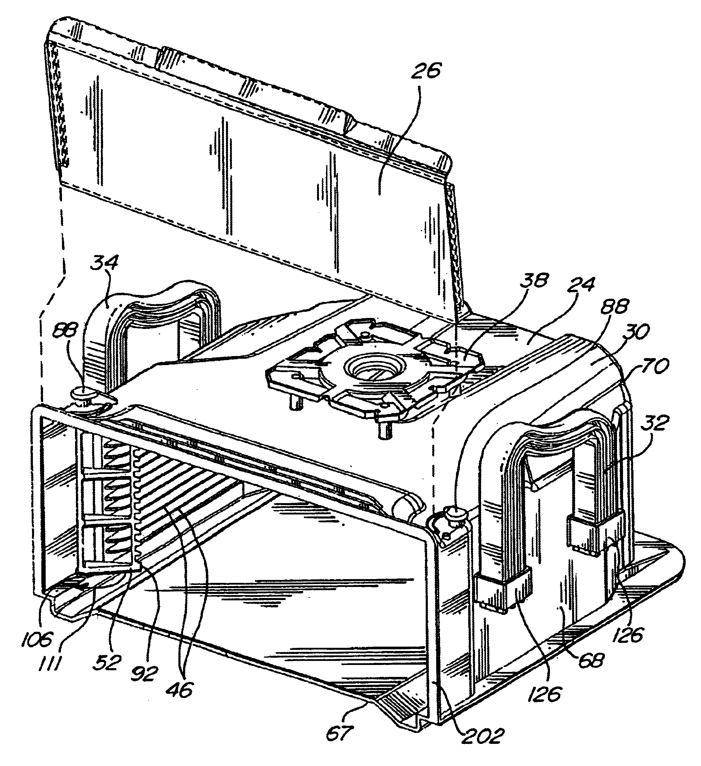
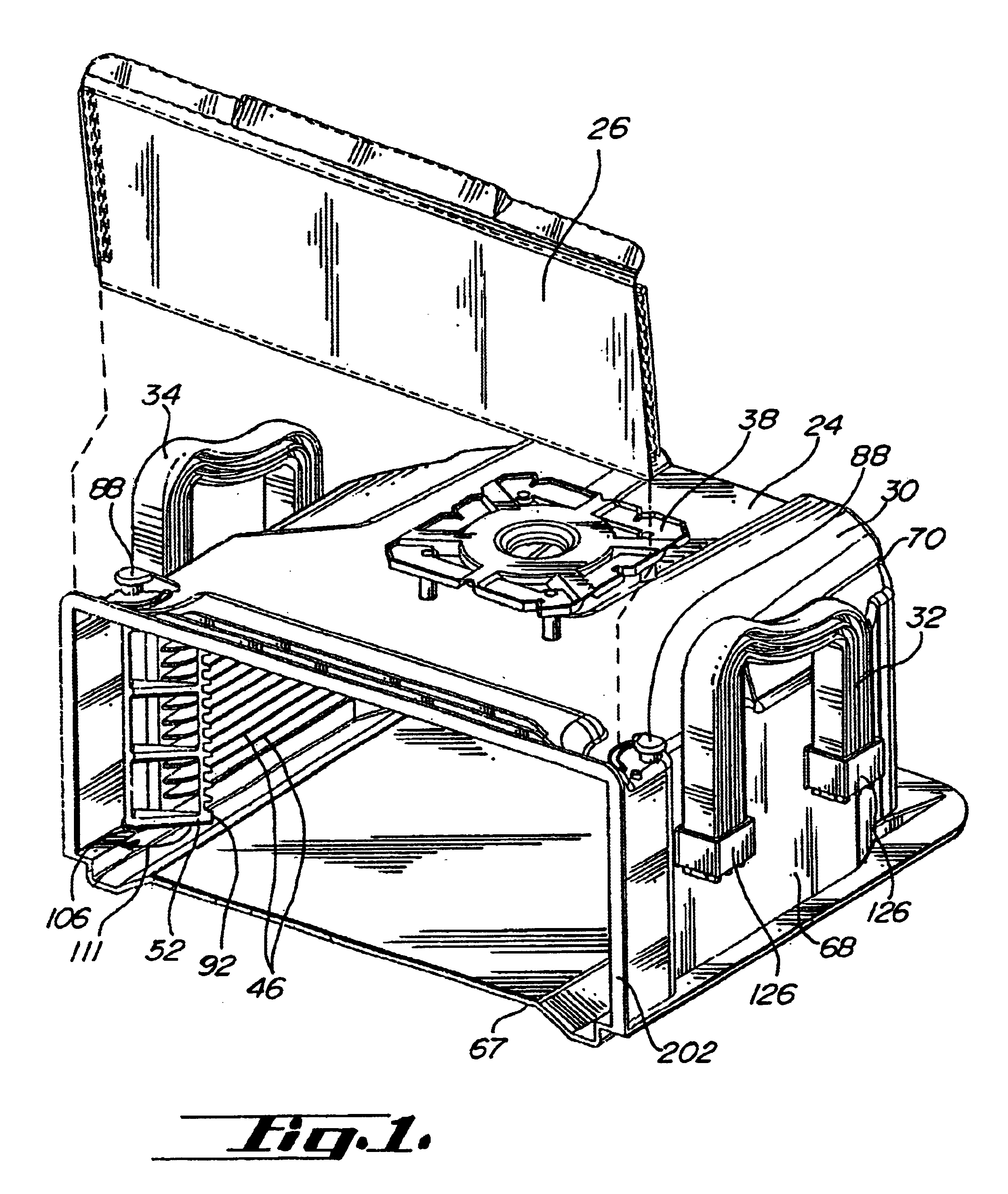
[0020]In the first cassette embodiment 20, the wafer retention members 52 have a shaft portion 74 which is rotatably connected to the top 82 and bottom 84 with knobs 88 attached to the retention members external the shell providing external control thereof. The retention members have an engagement portion 92 which can be configured as a saw tooth shape for engaging individual film frames edges 102 or potential wafers. Other configurations of the engagement portion may be utilized such as a soft resilient plastic strip, which is attached to the restraining member. The restraining member may operate on a cam surface 106 and be spring loaded at the top of the retention member 108 to provide suitable holding force when in the retention position or in the open position. FIG. 1 generally shows the restraining member in the retention position with an arrow 111 showing the motion towards the open position. FIG. 13 illustrates a plan view diagram of a cassette with a zone of insertion and wi...

second embodiment

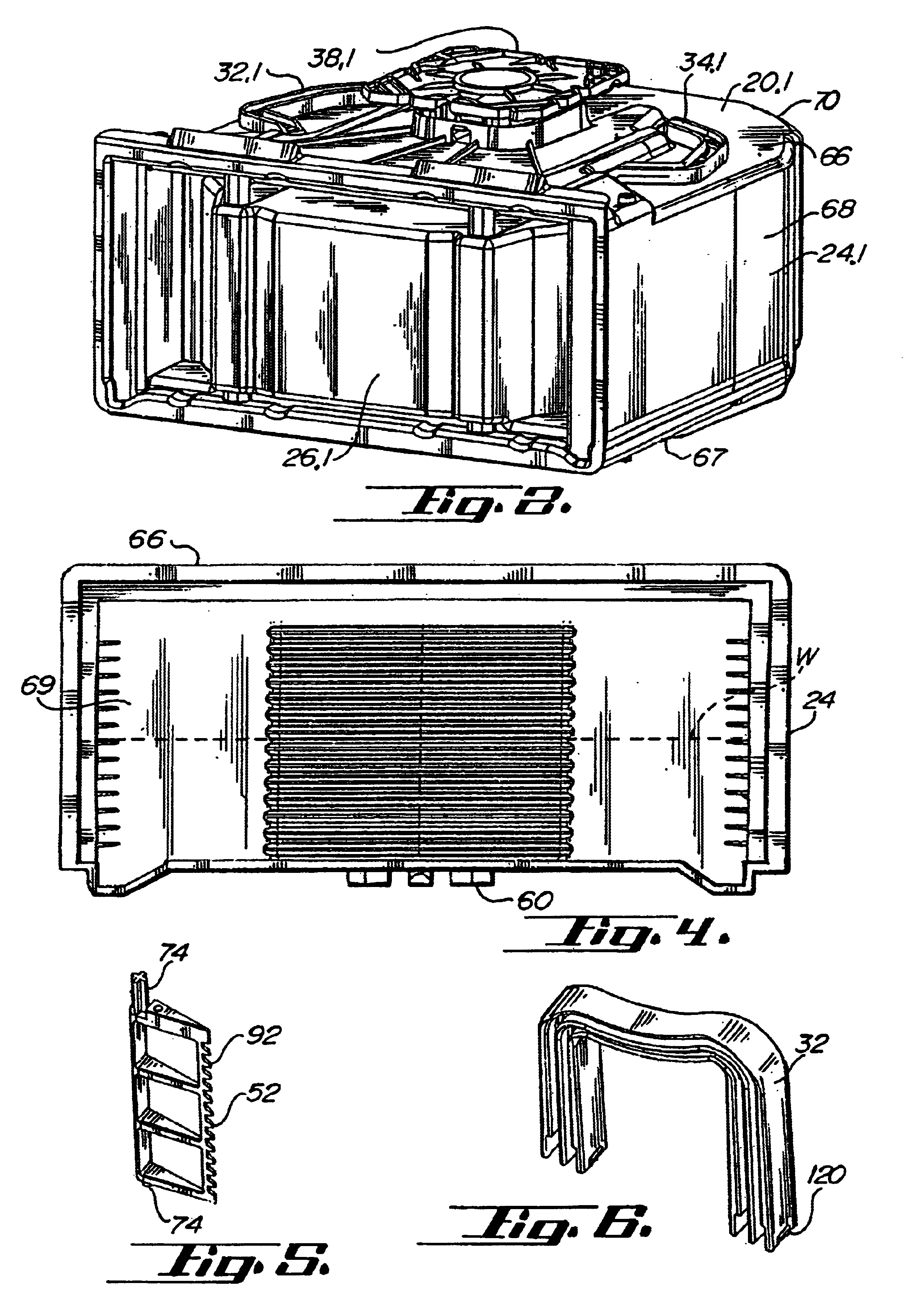
[0027]Referring to FIGS. 2, 3, 7, and 8, the cassette utilizes a door that is inserted within the open front of the enclosure portion. The door is a single generally rigid integral component having a plurality of inwardly extending structural recesses 210, may provide additional retention of the film frames w as well as providing structural rigidity and further horizontal surfaces 214 and vertical surfaces 216 to friction fit with interior surfaces 220 of the enclosure portion beyond the door flange or periphery of the open front. Generally, the inwardly extending structural recesses will preferably extend at least 1 and ½ inches beyond the forward edge 224 of the door opening. This door configuration also can be vacuum-formed.

[0028]Generally all of the components contained herein may be injection molded and the entire assembly may be assembled without utilization of metal fasteners. Generally plastic materials such as carbon fiber filled polycarbonate or PEEK or other plastics trad...


PUM


Abstract

A cassette, particularly suitable for storing film frames, in a preferred embodiment utilizes an integral shell portion with a plurality of shelves to support a plurality of axially aligned horizontally stacked film frames. A door, preferably vacuum-formed, covers the open front of the shell to enclose the film frames therein. The cassette may have a robotic top and collapsible handles. In a preferred embodiment the handles are U-shaped and slideably engaged with a pair of brackets integral with the sidewall. In another embodiment the handles pivot about an axis parallel to the top of the cassette and attach by a pair of split prongs insertable into a pair of receiving holes. A pair of film frame retention members are pivotally and rotatably attached at the sides of the shell inside the front opening. The restraints are pivotable between an open position where they are aligned with the sidewalls and pointing toward the open front to a film frame retention position where they are rotated to face inwardly in an approximately radial direction. The film frame retention members may be actuated by handles positioned on the top of the enclosure. Alternatively, the retention members may be automatically actuated by a helical cam mechanism with a engagement portion extending below the cassette to contact a surface upon which the cassette is placed. The members may be biased and spring loaded such that they remain in the retention position and / or the open position when so placed.

Description

[0001]This application claims benefit of U.S. Provisional Application No. 60 / 305,065, filed Jul. 12, 2001, said application being incorporated herein by reference.BACKGROUND OF THE INVENTION[0002]In the semiconductor processing industry semiconductor wafers undergo many steps during the conversion into useful integrated circuits. The wafers and intermediate components must be suitably stored and shipped intermediate the steps. Various containers are known for shipping and storing whole wafers. See for example U.S. Pat. Nos. 4,043,451; 5,788,082; and 5,915,562. The semiconductor processing industry has involved into utilizing larger and larger wafers as a beginning for processing into integrated circuits. Moreover, the industry has gone to thinner wafers, consequently these are substantially more fragile and valuable then previous wafers. The industry now seeks to utilize film frames comprising a circular rigid steel ring with a sheet of adhesive covered material to store and ship 30...

Claims


Application Information

Patent Timeline
IPC IPC(8): H01L21/67H01L21/673B65D85/86
CPCH01L21/67369H01L21/67383B65D85/38
Inventor DUBAN-HU, JOYNIGG, JAMESWISEMAN, BRIAN
Owner ENTEGRIS INC
Learn More