Lens diaphragm device, video camera incorporated with the same, and lens for the video camera

a technology of diaphragm and lens, which is applied in the direction of camera filters, instruments, television systems, etc., can solve the problems of resolution decline, resolution decline, resolution decline,

Inactive Publication Date: 2005-08-02
TAMRON
View PDF5 Cites 6 Cited by
  • Summary
  • Abstract
  • Description
  • Claims
  • Application Information

AI Technical Summary

Benefits of technology

[0008]To overcome the above mentioned disadvantage of the prior art, a lens diaphragm device according to the present invention includes diaphragm vanes that respectively have notches opposed to each other in a single plane perpendicular to an optical axis, and two of the vanes are moved close to and apart from the optical axis in the single plane so as to vary an aperture of the lens diaphragm. The lens diaphragm device also includes two optical filters used to reduce an amount of a beam of light passing through the diaphragm, and an aperture of the diaphragm defined by edges of the optical filters and the notches of the vanes is shaped to be asymmetrical about straight line which crosses the optical axis and is perpendicular to directions of the motion of the vanes.
[0009]With such a configuration of the present invention, when the aperture of the diaphragm is large, most of the light beam incident upon the diaphragm device passes between the notches of the vanes. As the aperture of the diaphragm is decreased, a major part of the light beam incident upon the diaphragm device is transmitted through the optical filters attached to the bottom of the notches. In this situation, the asymmetrical shape of the aperture of the diaphragm about the straight line crossing the optical axis and perpendicular to the directions of the motion of the vanes causes flares due to end faces of the optical filters to be dispersed, and thus, an adverse effect of the flares can be restrained.
[0010]In this way, attained is the lens diaphragm device that can avoid degradation of an image due to both the diffraction around the aperture of the diaphragm and the flares of the end faces of the optical filters.

Problems solved by technology

When the aperture of the lens diaphragm is extremely reduced, an aperture of the lens diaphragm causes diffraction which adversely results in a decrease in resolution.
Although the diffraction caused upon reducing the aperture can be restricted by the ND filters interposed in the aperture of the lens diaphragm, there arises another adverse phenomenon resulting in a decrease in resolution.
For instance, end faces of the ND filters, which define part of the aperture of the lens diaphragm along with the diaphragm vanes, reflect light into flares that reach a focusing plane, which resultantly is an additional cause of a decrease in resolution.
It is also known that such degradation of the image due to the flares may be caused because an aperture of the diaphragm varies depending upon a shape of the lens diaphragm and a manner in which the ND filters are affixed thereto.

Method used


Image

  • Lens diaphragm device, video camera incorporated with the same, and lens for the video camera
  • Lens diaphragm device, video camera incorporated with the same, and lens for the video camera
  • Lens diaphragm device, video camera incorporated with the same, and lens for the video camera

Examples


first embodiment

[0022]FIGS. 4(a) to 4(d) are diagrams showing variations in a shape of an aperture of the lens diaphragm at an aperture varied stepwise in the lens diaphragm device according to the present invention;

[0023]FIG. 5 is a front view showing two diaphragm vanes combined together for use in a second preferred embodiment of the stop diaphragm device according to the present invention;

[0024]FIG. 6 is a front view showing two diaphragm vanes combined together for use in a third preferred embodiment of the stop diaphragm device according to the present invention;

[0025]FIGS. 7(a) to 7(d) are diagrams showing variations in a shape of the aperture of the lens diaphragm at an aperture varied stepwise in the third preferred embodiment of the invention;

[0026]FIG. 8 is a 3-dimensional graph showing a distribution of transmissivity of a light beam passing through the lens diaphragm device at the aperture as shown in FIG. 7(d);

[0027]FIG. 9 is a graph showing an MTF defocusing property at a spatial fre...

third embodiment

[0033]FIG. 15 is a 3-dimensional graph showing a distribution of transmissivity of the light beam when ND filters of lower light transmissivity are used for the lens diaphragm according to the present invention;

[0034]FIG. 16 is a graph showing an MTF defocusing property at a spatial frequency of 10 per millimeters when a lens is in combination with the lens diaphragm having the distribution of transmissivity as shown in FIG. 15; and

[0035]FIG. 17 is a front view showing two diaphragm vanes combined together for use in a fourth preferred embodiment of the lens diaphragm device according to the present invention.

DESCRIPTION OF THE BEST MODE OF THE INVENTION

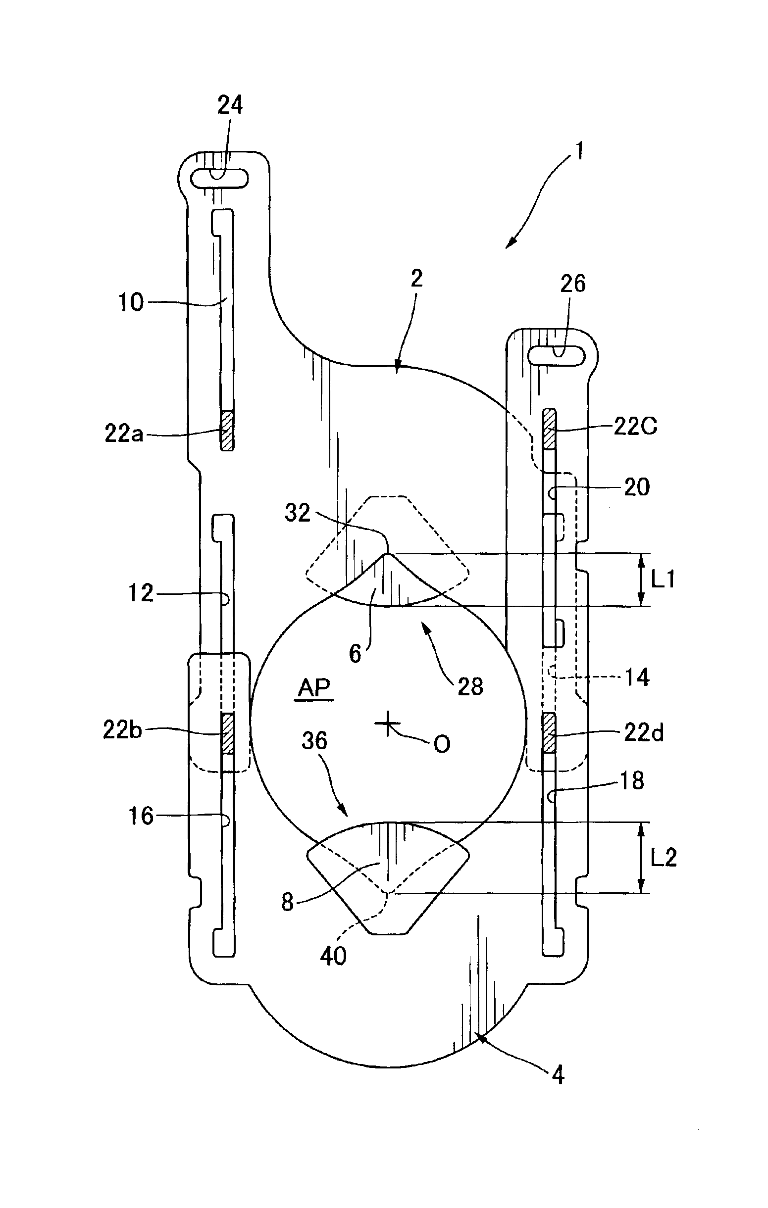
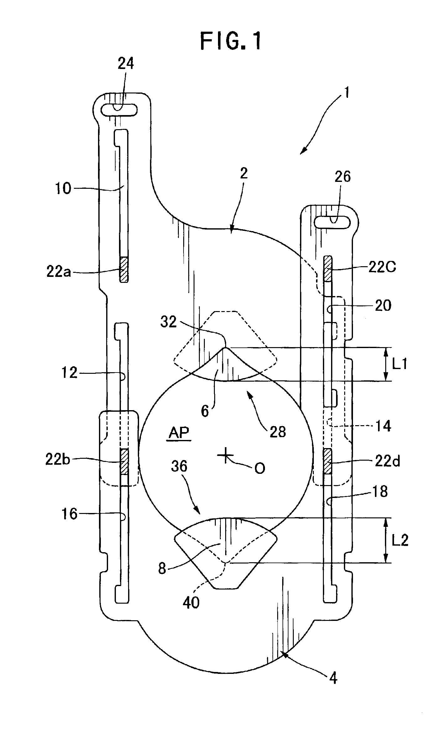
[0036]Preferred embodiments of a lens diaphragm device according to the present invention will now be described in conjunction with the accompanying drawings. First, referring to FIGS. 1 to 3 and 4(a) to 4(d), a first embodiment of the present invention will be detailed. FIG. 1 is a front view showing two lens diaphragm vanes combine...

second embodiment

[0045]As shown in FIG. 5, the second embodiment or a lens diaphragm device 201 includes a first diaphragm vane 2 having a notch 28 at its lower end, a second diaphragm vane 4 having a notch 36 at its upper end, an optical filter attached to the first vane 2, or namely, a first ND filter 206, a second ND filter 208 attached to the second vane 4, and an actuator (not shown) vertically moving two of the diaphragm vanes, and there is provided a diaphragm aperture AP between the notches 28 and 36. The first ND filter 206 shielding a deeper recess of the notch 28 is almost triangular in shape, and its end face shielding the diaphragm aperture is linear. The second ND filter 208 shielding a deeper recess of the notch 36 is shaped approximately like a fan, and it is similar in shape to the second ND filter of the first preferred embodiment.

[0046]In this embodiment, also, the first and second ND filters 206 and 208 are attached to the vanes so that a vertical distance L1 from an apex 32 of t...


PUM


Abstract

The present invention is directed to a lens diaphragm device that can avoid a degradation of an image due to both diffraction of a light beam and flares. The diaphragm device includes two diaphragm vanes (2 and 4) that respectively have notches (28 and 36) opposed to each other in a single plane perpendicular to an optical axis (O), and two of the vanes are moved close to and apart from each other in the single plane so as to vary an aperture of the lens diaphragm. The lens diaphragm device also includes two optical filters (6 and 8) used to reduce a quantity of a beam of light passing through the diaphragm, and an aperture of the diaphragm defined by edges of the optical filters and the notches of the vanes is shaped to be asymmetrical about straight line which crosses the optical axis and is perpendicular to directions of the motion of the vanes.

Description

DETAILED DESCRIPTION OF THE INVENTION[0001]1. Field of the Invention[0002]The present invention relates to a lens diaphragm device used in lens system for optical instrument, primarily for a vide camera, and more particularly, it relates to a lens diaphragm device that has ND filters attached to a couple of notched diaphragm vanes used for regulating light amount, to a video camera incorporated with such a lens diaphragm device, and to a lens for the video camera.[0003]2. Prior Art[0004]In general, a lens used for various cameras such as a video camera has a lens diaphragm device having a couple of diaphragm vanes where notches respectively defined in the vanes are capable of variably eclipse light flux to adjust an amount of light. In some recently developed video cameras, imaging devices are highly sensitive, and hence, an aperture of the lens diaphragm must be reduced when shooting a highly luminant object. When the aperture of the lens diaphragm is extremely reduced, an aperture...

Claims


Application Information

Patent Timeline
Patent Type & Authority Patents(United States)
IPC IPC(8): G03B9/02G02B5/00H04N5/225G03B11/00
CPCG02B5/005G03B9/02H04N5/2254
Inventor WATANABE, YUKOINOUE, MICHIOMIYAUCHI, YASUNORI
Owner TAMRON
Why Eureka
Try Eureka