Cable tray apparatus and method

a cable tray and cable tray technology, applied in the field of cable tray apparatus, can solve the problems that the existing cable tray and rack system, while structurally sound, cannot meet the need of routing the increased volume of cable required

Inactive Publication Date: 2005-08-09
JETTE ROGER
View PDF56 Cites 32 Cited by
  • Summary
  • Abstract
  • Description
  • Claims
  • Application Information

AI Technical Summary

Benefits of technology

[0009]According to one aspect of the present disclosure, a cable tray apparatus for use with a ladder-type cable tray having a pair of parallel spaced apart rails interconnected by a plurality of rungs is disclosed. The cable tray apparatus includes an elongate flexible spine member selectively bendable into a number of different configurations, and a plurality of spaced apart hangers attached to the elongate spine member along the length thereof, each of the plurality of hangers defining a partially enclosed area configured and dimensioned to receive at least one cable therein, wherein each of the plurality of hangers includes a support bracket integrally formed therewith for removably attaching the hanger to at least one of the pair of spaced apart rails of the ladder-type cable tray.

Problems solved by technology

Some existing cable tray and rack systems while structurally sound cannot meet the need of routing the increased volume of cable required.

Method used


Image

  • Cable tray apparatus and method
  • Cable tray apparatus and method
  • Cable tray apparatus and method

Examples


Embodiment Construction

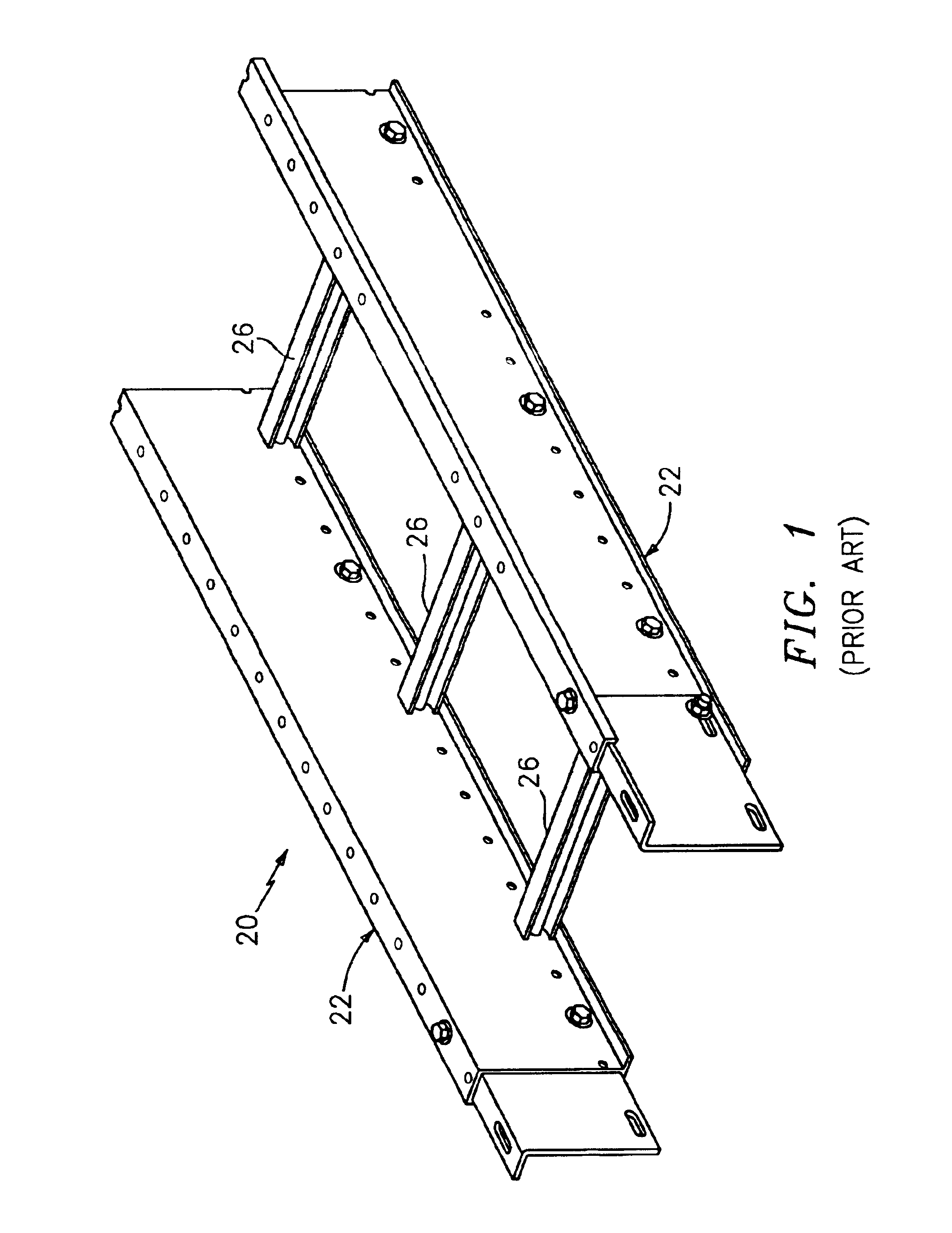
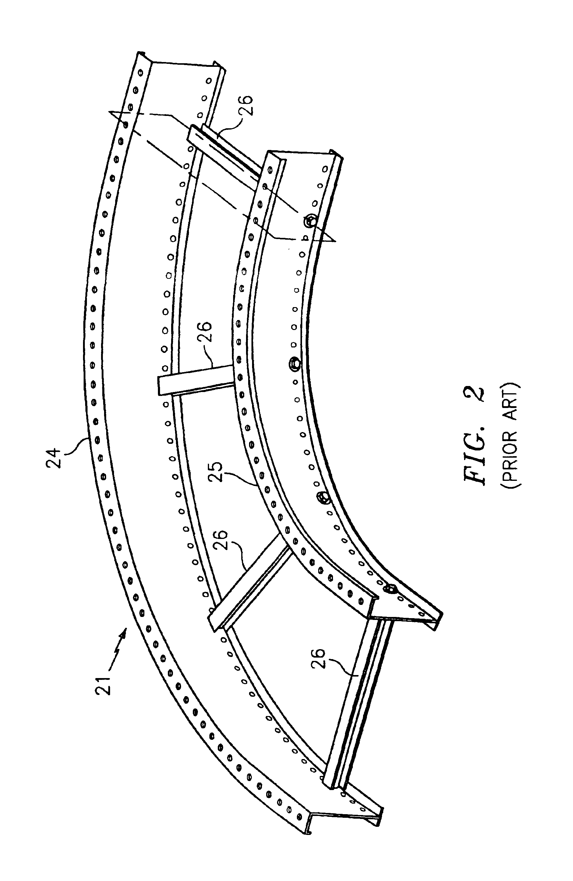
[0029]As seen in FIG. 1, a prior art ladder-type cable tray is generally designated as 20 and includes first and second generally parallel side rails 22 and a plurality of spaced apart rungs 26 secured to and extending generally transversely between the side rails 22. In addition, as seen in FIG. 2, a prior art arcuate section of cable tray is generally designated as 21 and includes a pair of curved concentric spaced apart side rails 24, 25 connected by rungs, each also designated 26.

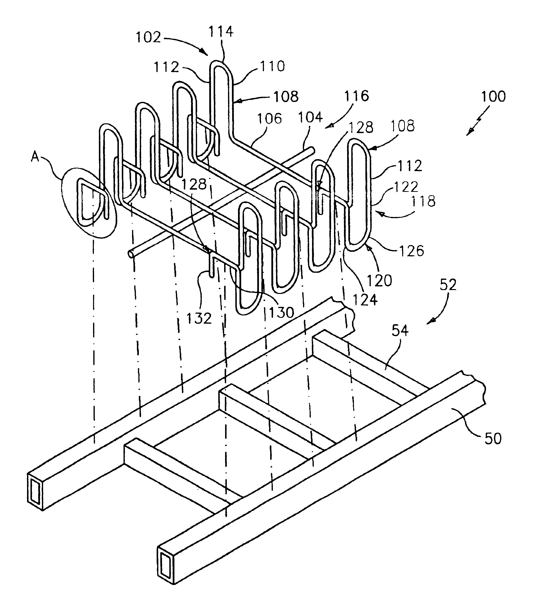
[0030]Preferred embodiments of the presently disclosed cable tray apparatus will now be described in detail with reference to the drawing figures wherein like reference numerals identify similar or identical elements. Referring now in specific detail to FIGS. 3-8, and initially to FIGS. 3-7, one embodiment of a cable tray apparatus, in accordance with the present disclosure, is shown generally as 100. Cable tray apparatus 100 includes a plurality of spaced apart hangers 102 and a flexible spine 104, int...


PUM


Abstract

A cable tray apparatus for use with a ladder-type cable tray having a pair of parallel spaced apart rails interconnected by a plurality of rungs is disclosed. The cable tray apparatus includes an elongate flexible spine member selectively bendable into a number of different configurations, and a plurality of spaced apart hangers attached to the elongate spine member along the length thereof, each of the plurality of hangers defining a partially enclosed area configured and dimensioned to receive at least one cable therein, wherein each of the plurality of hangers includes a support bracket integrally formed therewith for removably attaching the hanger to at least one of the pair of spaced apart rails of the ladder-type cable tray. The present disclosure also relates to methods of using the cable tray subassemblies disclosed herein in conjunction with ladder-type cable trays.

Description

CROSS-REFERENCE TO RELATED APPLICATION[0001]The present application claims the benefit of and priority to U.S. Provisional Patent Application Ser. No. 60 / 361,437 filed on Mar. 4, 2002, the entire contents of which are incorporated herein by reference.BACKGROUND[0002]1. Technical Field[0003]The present disclosure relates to a cable tray apparatus and, more particularly, to a cable tray apparatus for attachment to separate structural members, for example, a ladder-type cable tray. The present disclosure also relates to methods of using the cable tray subassemblies disclosed herein in conjunction with separate structural members, such as ladder-type cable trays.[0004]2. Background of Related Art[0005]Conventional ladder-type cable trays generally include a pair of spaced apart parallel and / or concentric side rails and a series of spaced apart rungs typically extending transversely between the rails for cradling cables, wiring, tubes and the like, such as for computer networks, telecomm...

Claims


Application Information

Patent Timeline
Patent Type & Authority Patents(United States)
IPC IPC(8): F16L3/00F16L3/26H02G3/04
CPCH02G3/0443H02G3/0456
Inventor JETTE, ROGER
Owner JETTE ROGER
Why Eureka
Try Eureka