Cable tray cable routing system

a cable routing and cable tray technology, applied in the direction of rod connections, machine supports, other domestic objects, etc., can solve the problems of time-consuming, costly, and sharp edges of cable duct pathways

Active Publication Date: 2013-04-23
PANDUIT
View PDF43 Cites 24 Cited by
  • Summary
  • Abstract
  • Description
  • Claims
  • Application Information

AI Technical Summary

Problems solved by technology

As a result, installation of the typical cable basket or cable duct pathway is time consuming, costly and creates sharp edges.

Method used


Image

  • Cable tray cable routing system
  • Cable tray cable routing system
  • Cable tray cable routing system

Examples


Embodiment Construction

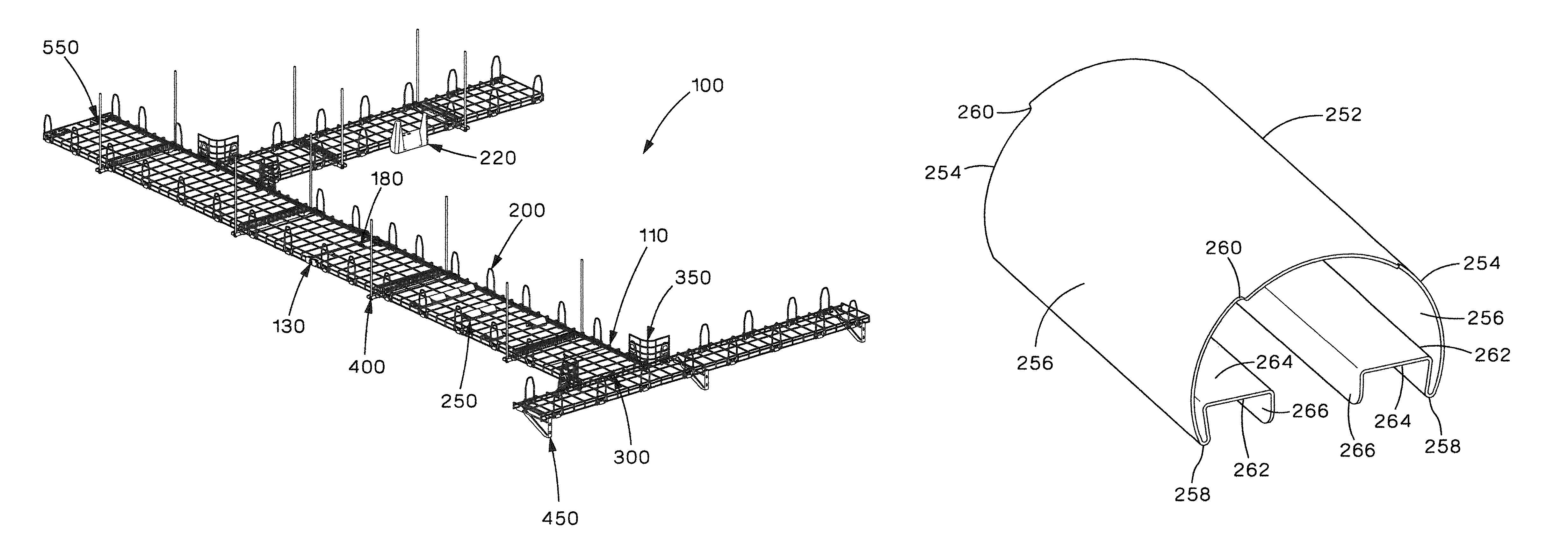
[0095]FIG. 1 illustrates a top perspective view of the cable tray cable routing system 100 of the present invention. The cable tray cable routing system 100 is an overhead system with no integral sidewalls. The cable tray cable routing system 100 includes sidewall joiner brackets 130 (see FIGS. 3-7) and center position joiner brackets 180 (see FIGS. 8-11) for securing adjacent cable trays. The cable tray cable routing system 100 includes snap-on sidewalls 200 (see FIGS. 12-17) for installing sidewalls where cable retention is highly required. The cable tray cable routing system 100 includes side spill downs 220 (see FIGS. 18-21) and drop down waterfall devices 250 (see FIGS. 22-28) for routing cables to and from the system. The cable tray cable routing system 100 includes intersect joiner brackets 300 (see FIGS. 29-38) and corner radius devices 350 (see FIGS. 39-44). Finally, the cable tray cable routing system 100 includes trapeze brackets 400 (see FIGS. 45-51), cantilever wall mou...


PUM


Abstract

The present invention is directed to a cable routing system with a drop down cable routing device that routes cables from the cable routing system. The drop down cable routing device is attached to a cable tray of the cable routing system. The drop down cable routing device includes an outer shell and an inner core. The outer shell has downwardly extending sides. A bottom of each side of the outer shell includes a mating flange extending therefrom. The inner core is positioned within the outer shell. The inner core has a base with sides and mating flanges extending downwardly from the sides. The mating flanges of the outer shell engage the mating flanges of the inner core to secure the outer shell and the inner core together.

Description

CROSS-REFERENCE TO RELATED APPLICATIONS[0001]This application claims priority to U.S. Provisional Application No. 61 / 346,205, filed May 19, 2010, the subject matter of which is hereby incorporated by reference in its entirety.FIELD OF THE INVENTION[0002]The present invention relates to a cable tray system, and more particularly, to a wire cable tray system for routing cables in various overhead applications.BACKGROUND OF THE INVENTION[0003]Overhead cable routing systems typically include a cable basket or a cable duct. The cable basket or cable duct include integral sidewalls. Various routing devices are installed on the cable basket or cable duct during installation. Often the sidewalls of the cable basket or cable duct need to be cut when a tee, cross or right angle pathway is created. As a result, installation of the typical cable basket or cable duct pathway is time consuming, costly and creates sharp edges.[0004]It is desirable to provide a cable routing system that refrains fr...

Claims


Application Information

Patent Timeline
Patent Type & Authority Patents(United States)
IPC IPC(8): F16L3/00
CPCH02G3/0443H02G3/0608Y10T403/3906F16B2/245F16B7/0493A47B55/02
Inventor DAVIS, DAVID R.BROUWER, SHAUN P.WASZAK, DENNIS J.RAMEY, SAMUEL C.HARTMAN, SCOTT R.NICOLI, ROBERT
Owner PANDUIT
Why Eureka
Try Eureka