Design method for cable laying and cable laying system

A cable laying and design method technology, applied in the direction of calculation, electrical digital data processing, special data processing applications, etc., can solve the problems of great difference between cable length and estimated length, incomplete equipment positioning information, and affecting project progress, etc., to eliminate Re-routing problems, accurate calculation of cable length, reasonable effect of cable channel ratio

Inactive Publication Date: 2016-10-12
CHINA ENERGY ENG GRP GUANGDONG ELECTRIC POWER DESIGN INST CO LTD
View PDF4 Cites 28 Cited by
  • Summary
  • Abstract
  • Description
  • Claims
  • Application Information

AI Technical Summary

Problems solved by technology

However, at present, when laying cables in nuclear power plants, the cable laying path is not planned in detail, and the reasonable distribution of cable channels cannot be effectively controlled. It is completely carried out by the construction experience of the on-site construction unit, and the blindness is large. The length of the cable is manually estimated according to the layout of the plane channel, resulting in a huge difference between the cable length and the estimated length, low design efficiency and large errors; and the location information of the field equipment is incomplete. Lack of instrument positioning information in the design stage often leads to re-laying due to unreasonable cable laying, causing investment waste and affecting project progress

Method used


Image

  • Design method for cable laying and cable laying system

Examples


Embodiment Construction

[0025] Embodiments of the present invention are described in detail below in conjunction with accompanying drawings:

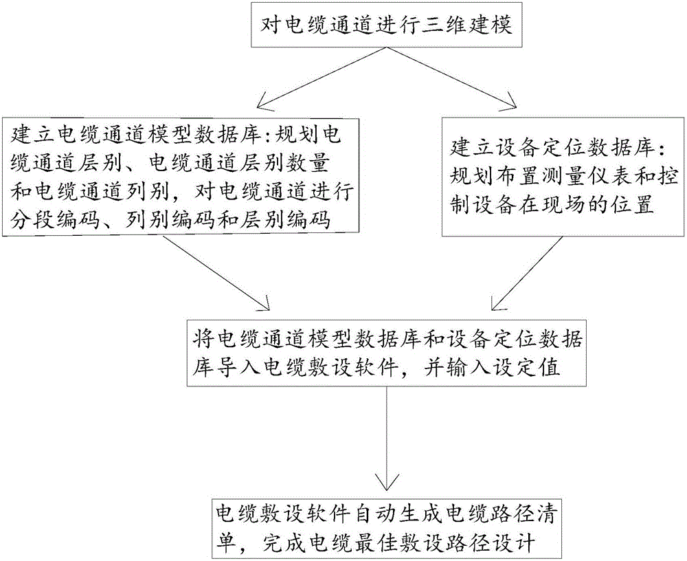
[0026] Such as figure 1 As shown, a cable laying design method includes the following steps:

[0027] Carry out three-dimensional modeling of the cable channel, so that each position in the cable channel has three-dimensional positioning information;

[0028] Establish a cable channel model database: plan the cable channel layer, the number of cable channel layers and the cable channel column, and perform segmental coding, column coding and layer coding on the cable channel;

[0029] Establish equipment positioning database: plan and arrange the location of measuring instruments and control equipment on site;

[0030] Import the cable channel model database and equipment positioning database into the cable laying software, and input the set values;

[0031] The cable laying software automatically generates a list of cable paths to complete the design of the...


PUM


Abstract

The invention relates to a design method for cable laying and a cable laying system. The method comprises following steps: creating a three-dimensional model for a cable channel; setting up a cable channel model database; planning layers of the cable channel, the number of layers of the cable channel and the arrays of the cable channel, and encoding the cable channel in a segmented manner, arrays and layers; setting up an equipment positioning database; planning positions of a measuring instrument and control equipment on the spot; guiding the cable channel model database and the equipment positioning database into cable laying software and inputting setting value; and finishing a best cable laying path design after a cable laying path list is automatically generated by cable laying software. The design method for cable laying and the cable laying system have following beneficial effects: by automatically generating the cable path list, deign efficiency is increased; by effectively planning the cable laying path, cable bridges can be reasonably distributed; the problem of repeatedly laying due to unresonable laying of circuits is eliminated; investment waste is avoided; engineering speed is ensured; a clear cable path is provide for a foundation of precise cable length calculations.

Description

technical field [0001] The invention relates to the technical field of cable laying, in particular to a cable laying design method and a cable laying system. Background technique [0002] The cable is a bridge connecting the control system and the controlled equipment. The cable laying path is reasonable to ensure reliable signal transmission and safe operation of the power plant. However, at present, when laying cables in nuclear power plants, the cable laying path is not planned in detail, and the reasonable distribution of cable channels cannot be effectively controlled. It is completely carried out by the construction experience of the on-site construction unit, and the blindness is large. The length of the cable is manually estimated according to the layout of the plane channel, resulting in a huge difference between the cable length and the estimated length, low design efficiency and large errors; and the location information of the field equipment is incomplete. The ...

Claims


Application Information

Patent Timeline
Patent Type & Authority Applications(China)
IPC IPC(8): G06F17/50
CPCG06F30/367
Inventor 黄玉娴王小博刘宇穗林伟波肖雄军
Owner CHINA ENERGY ENG GRP GUANGDONG ELECTRIC POWER DESIGN INST CO LTD
Why Eureka
Try Eureka