Heat exchanger assembly having a heated condensate drainage system

a technology of condensate drainage and heat exchanger, which is applied in the direction of defrosting, refrigeration machines, domestic cooling devices, etc., can solve the problems of condensate freezing and damage to the outdoor heat exchanger assembly, and achieve the effect of improving heat transfer efficiency and simple elegan

Active Publication Date: 2017-08-29
MAHLE INT GMBH
View PDF5 Cites 2 Cited by
  • Summary
  • Abstract
  • Description
  • Claims
  • Application Information

AI Technical Summary

Benefits of technology

[0006]An advantage of the heat exchanger assembly disclosed herein is that it provides a simple elegant solution to extract and convey condensate away from the heat exchanger assembly. The conveyance of condensate away from the heat exchanger assembly minimalizes the obstruction of airflow through the core, thereby improving heat transfer efficiency. Another advantage is that during the defrost cycle, the elongated members, or pins, conduct heat energy from the manifold to melt any ice that may have built up during the evaporator mode to clear a path for condensate to drain from the drainage tray.

Problems solved by technology

If the outdoor ambient temperature is below the freezing temperature for water, the condensate may freeze and damage the outdoor heat exchanger assembly.

Method used


Image

  • Heat exchanger assembly having a heated condensate drainage system
  • Heat exchanger assembly having a heated condensate drainage system
  • Heat exchanger assembly having a heated condensate drainage system

Examples


Embodiment Construction

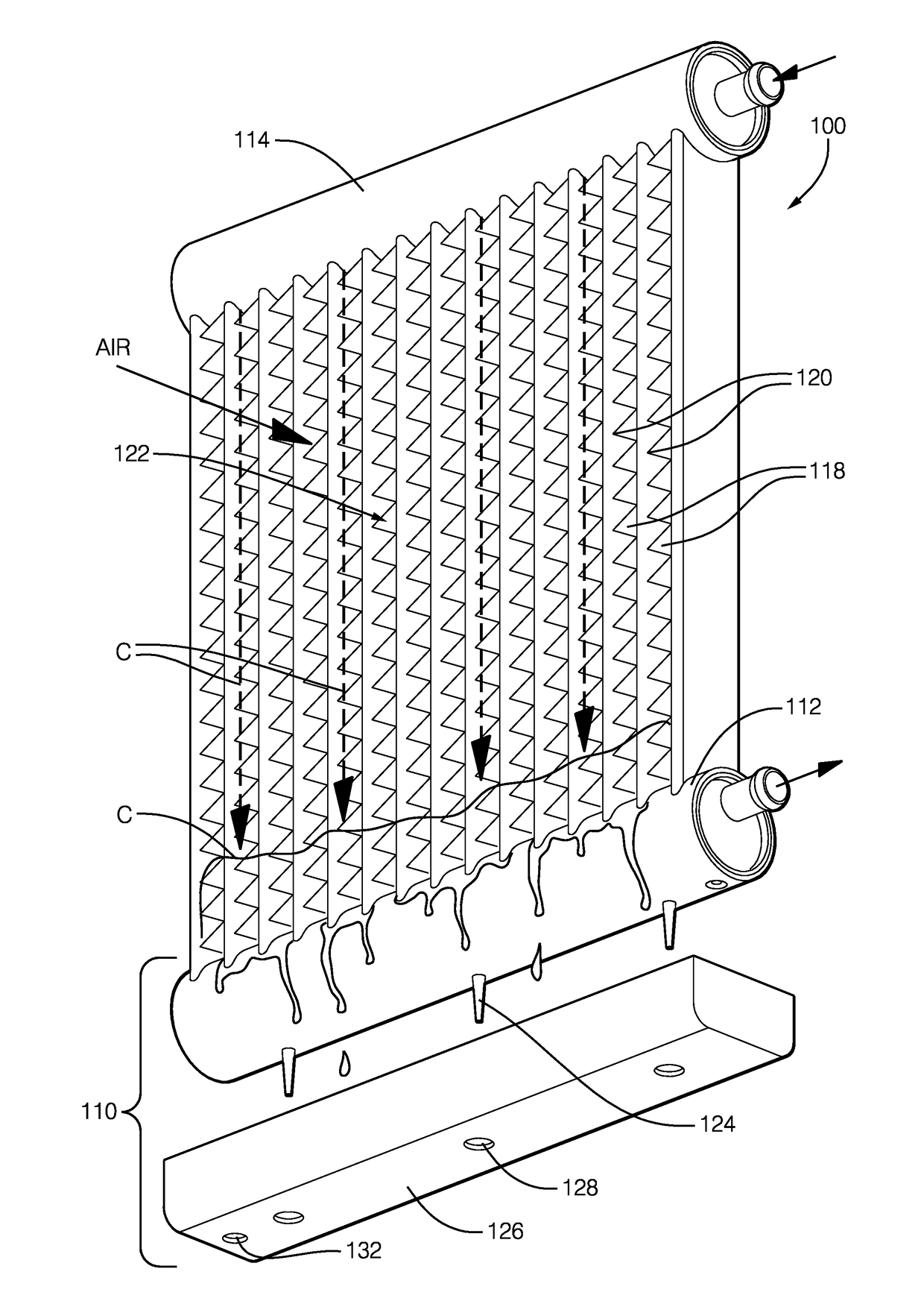
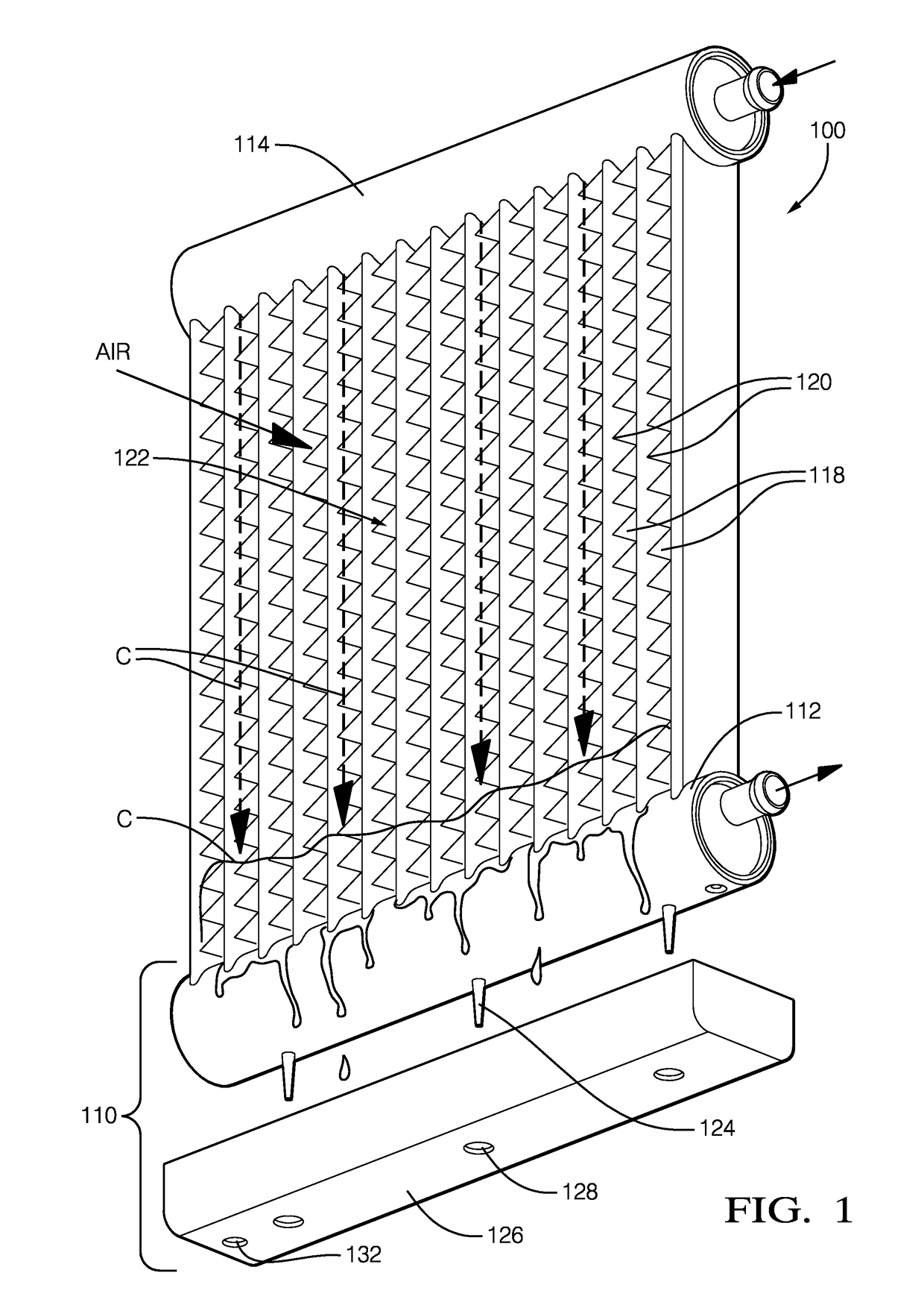
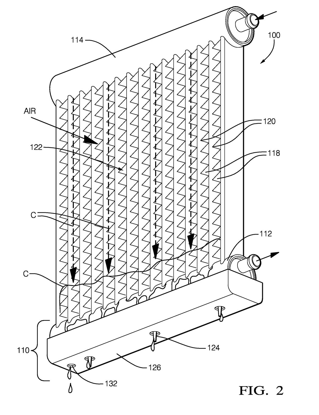
[0011]A heat pump system typically includes an indoor heat exchanger assembly and an outdoor heat exchanger assembly connected in series within a refrigerant loop. The heat exchanger assemblies are also known as heat exchanger coils. A two-phase refrigerant, such as R-134a or R-1234yf, is circulated through the refrigerant loop by a compressor. When the heat pump system is operating in heating mode, the suction side of the compressor receives a low pressure vapor phase refrigerant from the outdoor heat exchanger assembly, which is functioning as an evaporator, after scavenging heat from the outside ambient air. The compressor than compresses the low pressure vapor phase refrigerant into a hot high pressure vapor phase refrigerant, which is then discharged to the indoor heat exchanger, which functions as a condenser. As the high pressure vapor phase refrigerant is condensed to a high pressure liquid phase refrigerant in the indoor heat exchanger assembly, heat energy is dispersed to ...


PUM


Abstract

The disclosure presents a heat exchanger assembly for a heat pump system, having a heated condensate drainage system. The heat exchanger assembly includes a manifold with a plurality of pins extending substantially in the direction of gravity. A condensate drainage tray is positioned beneath the manifold. The drainage tray includes a plurality of drainage holes corresponding with the number and position of the pins. The pins extend from the manifold and through the corresponding the drainage holes of the drainage tray. Each of the plurality of pins includes a diameter smaller than the diameter of the drainage hole to allow for condensate to drain through the drainage hole. At least one of the pins includes a distal end and is tapered toward the distal end. The drainage tray may be tilted with respect to the manifold.

Description

TECHNICAL FIELD OF INVENTION[0001]The present invention relates to a heat exchanger assembly for a heat pump system; more particularly, to a heat exchanger assembly having a condensate drainage system; still more particularly, to a heated condensate drainage system.BACKGROUND OF INVENTION[0002]A typical residential / commercial heat exchanger assembly used in a heat pump system, or otherwise known as a heat exchanger coil, includes a first manifold, a second manifold, and a plurality of refrigerant tubes hydraulically connecting the manifolds for refrigerant flow there between. Corrugated fins interconnect adjacent refrigerant tubes to increase the available heat transfer area, as well as to increase the structural integrity of the heat exchanger assembly. The refrigerant tubes and interconnecting corrugated fins together define the core of the heat exchanger. The heat exchanger assembly may function alternatively in evaporator mode or condenser mode, depending on the needs of the hea...

Claims


Application Information

Patent Timeline
Patent Type & Authority Patents(United States)
IPC IPC(8): F25D21/14F25B39/00
CPCF25D21/14F25B39/00F25B2400/01
Inventor FORREST, WAYNE O.
Owner MAHLE INT GMBH
Why Eureka
Try Eureka