Filter device

a filter device and filter technology, applied in the direction of fluid couplings, lubricant mounting/connection, separation processes, etc., can solve the problems of affecting the operation of the filter device, so as to avoid damaging the banking up pressure in the system, improve the filter device, and ensure the effect of reliable operation

Inactive Publication Date: 2007-06-19
HYDAC FILTERTECHNIK GMBH
View PDF18 Cites 2 Cited by
  • Summary
  • Abstract
  • Description
  • Claims
  • Application Information

AI Technical Summary

Benefits of technology

[0006]Objects of the present invention are provided to improve filter devices such that the damaging banking-up pressure in the system is avoided while reliable operati...

Problems solved by technology

For example, in a hydraulic motor and a hydraulic pump pressure peaks can damage the sealing elements.
Therefore, the known filter devices are structurally large and expensive to produce.
In this known approach, the thermostat can produce a banking-up pressure which leads to damaging pressure peaks in the upstream units especially at low temperatures of the hydraulic medium within the hydraulic circuit.
As a res...

Method used


Image

  • Filter device
  • Filter device
  • Filter device

Examples


Embodiment Construction

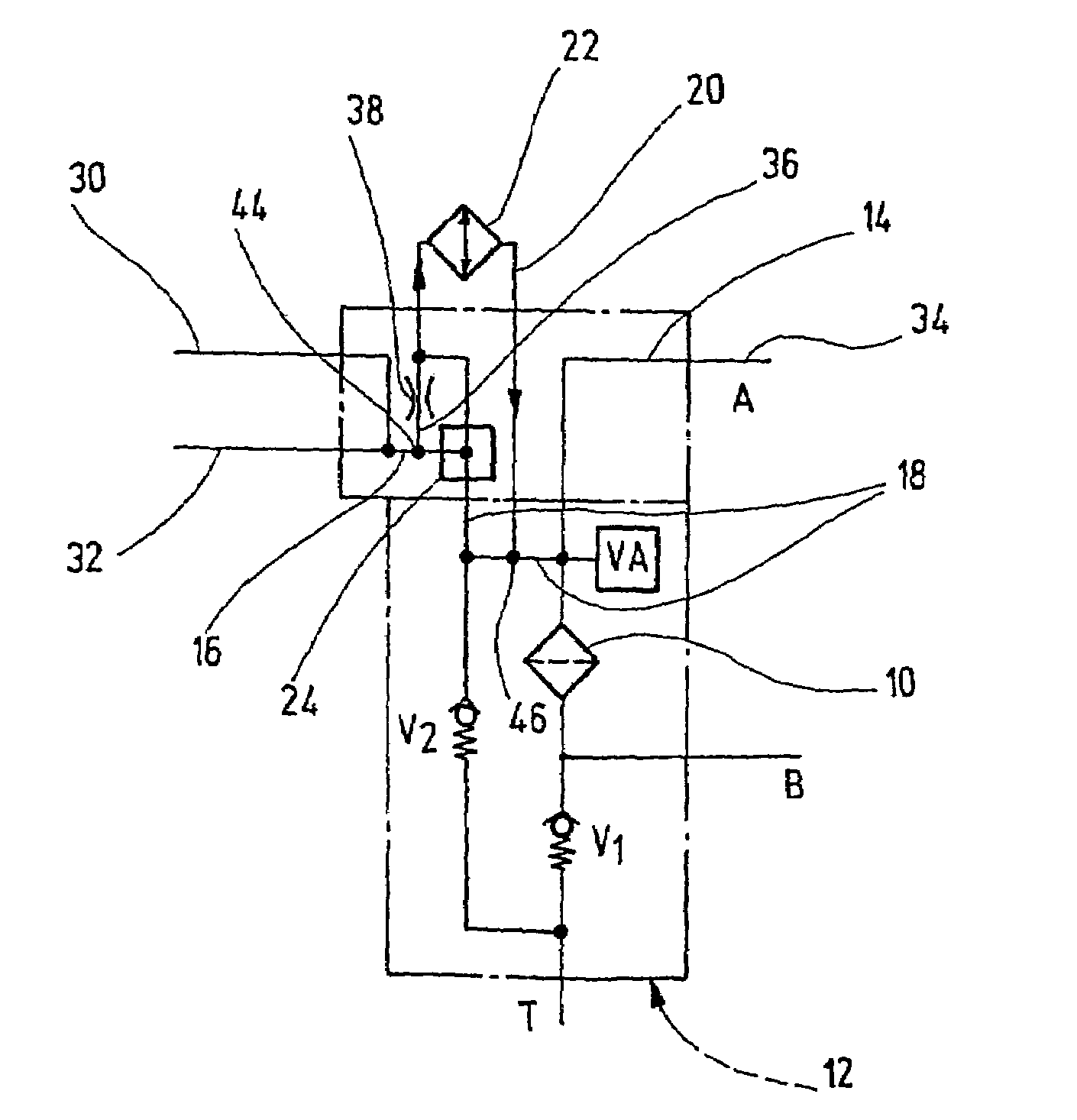
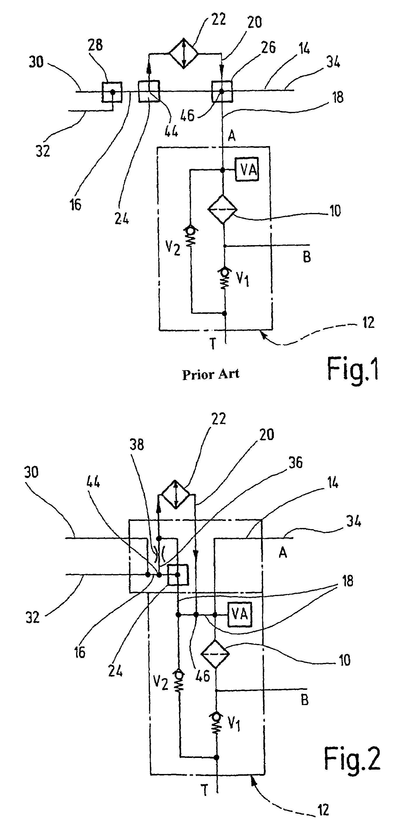
[0019]The known or conventional filter device shown in FIG. 1 has a filter unit 10 of conventional design. The filter unit 10 is a component of a return line intake filter 12; its important components being encircled in FIG. 1 with a broken-line frame. The return line intake filter 12 is provided with a fouling display VA which delivers an optical or other signal indication with respect to the state of fouling of the actual filter unit 10. A spring-loaded check valve V2, in the manner of a bypass valve, is connected to the bypass line of the filter unit 10. If the filter unit 10 is clogged by fouling, the pretensioned bypass valve V2 opens to the tank T. In this way, dangerous pressure peaks cannot build up in the system. In the flow direction downstream of the filter unit 10, the intake connection B is provided which, in conjunction with the spring-loaded check valve V1, produces a pretensioning pressure which ensures that the oil column in the hydraulic circuit 14 cannot separate....


PUM

PropertyMeasurementUnit
Temperatureaaaaaaaaaa
Pressureaaaaaaaaaa
Flow rateaaaaaaaaaa

Abstract

A filter device includes at least one filter unit (10), connectable to a hydraulic circuit (14), with at least one supply line (16), one discharge line (18), and at least one cooling unit (22). The cooling unit is connected to a secondary branch line (20), is connected to the hydraulic unit (14) parallel to the supply line (16), and is supplied with a hydraulic medium by a switching device (24) once a predetermined temperature threshold value of the hydraulic medium to be cooled is attained. A permanent supply (36) for the cooling unit (22) is provided in the direction of flow of the hydraulic medium in the supply line (18) before the switching device (24). This permanent supply (36), connected in parallel to the switching device (24), flows into the secondary branch line (20) to control the volume flow in reverse flow according to the fluid temperature. A partial flow of the hydraulic medium in the supply line directly reaches the cooling unit at low or reduced temperatures, at which the switching device has not yet been actuated to ensure that the cooling unit is permanently supplied with the hydraulic medium.

Description

FIELD OF THE INVENTION[0001]The present invention relates to a filter device with at least one filter unit which can be connected to a hydraulic circuit, with at least one supply line and one drain line. At least one cooling unit is connected in a secondary branch line and is connected parallel to the supply line into the hydraulic circuit. At a definable temperature threshold of the hydraulic medium to be cooled is supplied to the cooling unit by a changeover means.BACKGROUND OF THE INVENTION[0002]In known approaches, as are freely available on the market, filter devices are used in all types of hydraulic systems, especially in construction machines. Filter units, called return line intake filters, are in the return lines of the respective hydraulic system discharge. The return lines are combined into collectors which ensure central inflow of the fouled fluid or hydraulic medium to the respective return line intake filter unit. After filtration, the cleaned fluid is relayed to an i...

Claims


Application Information

Patent Timeline
IPC IPC(8): B01D35/00B01D35/147F01M5/00B01D35/02F01M11/03F15B21/041F15B21/0423
CPCB01D35/0276F15B21/041F15B21/042B01D35/147F01M2011/033F15B2211/615F15B2211/62F15B21/0423
Inventor WILKENDORF, WERNER
Owner HYDAC FILTERTECHNIK GMBH
Why Eureka
Try Eureka