Telescoping Wire Cable Tray System

a cable tray and telescopic technology, applied in the direction of machine supports, building scaffolds, other domestic objects, etc., can solve the problems of sharp cutting and deburring of cable trays during installation, and the time-consuming and labor-intensive cutting and deburring of cable trays

Active Publication Date: 2011-01-13
PANDUIT
View PDF41 Cites 25 Cited by
  • Summary
  • Abstract
  • Description
  • Claims
  • Application Information

AI Technical Summary

Problems solved by technology

Cutting and deburring cable trays during installation

Method used


Image

  • Telescoping Wire Cable Tray System
  • Telescoping Wire Cable Tray System
  • Telescoping Wire Cable Tray System

Examples


Embodiment Construction

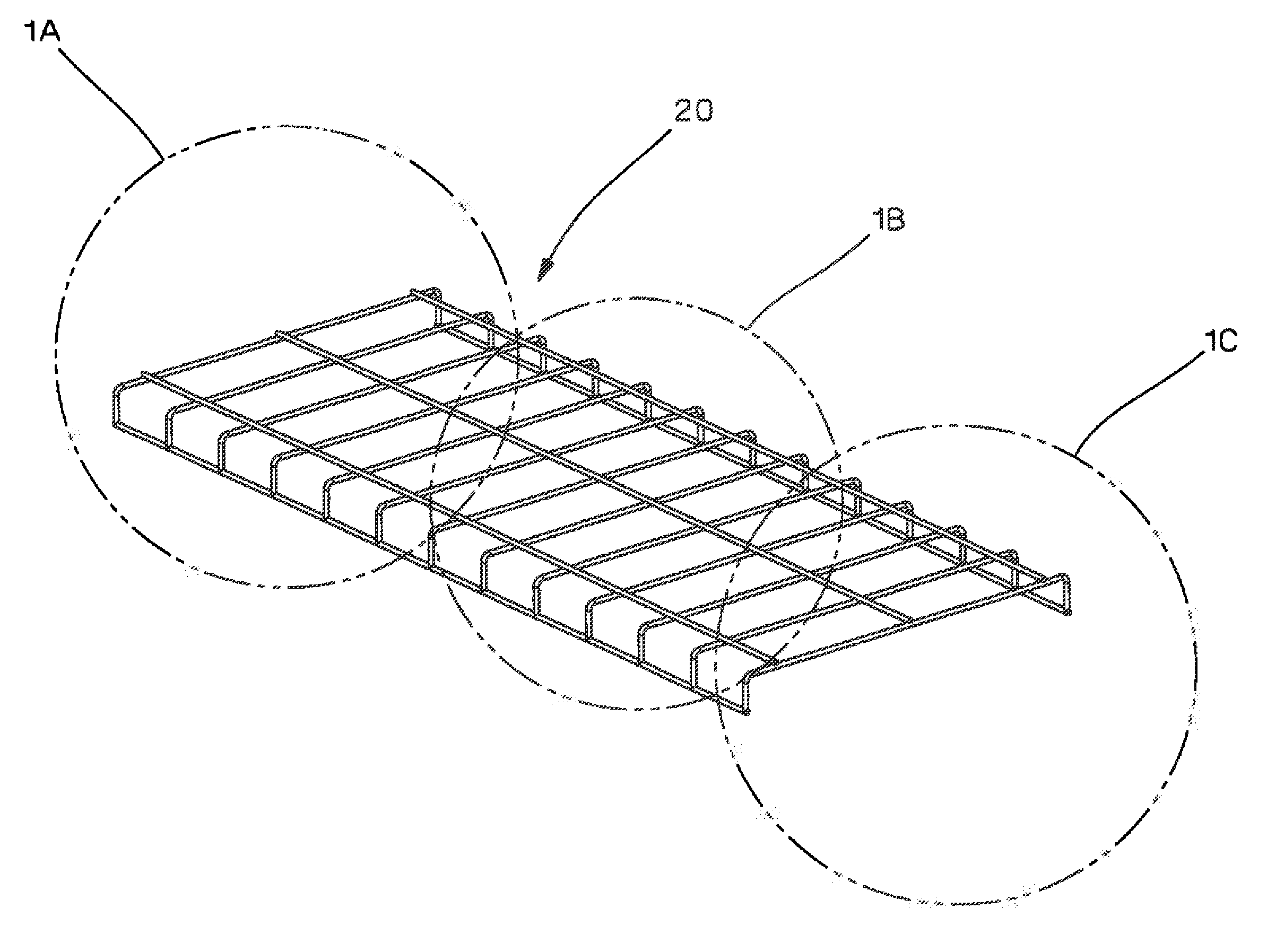
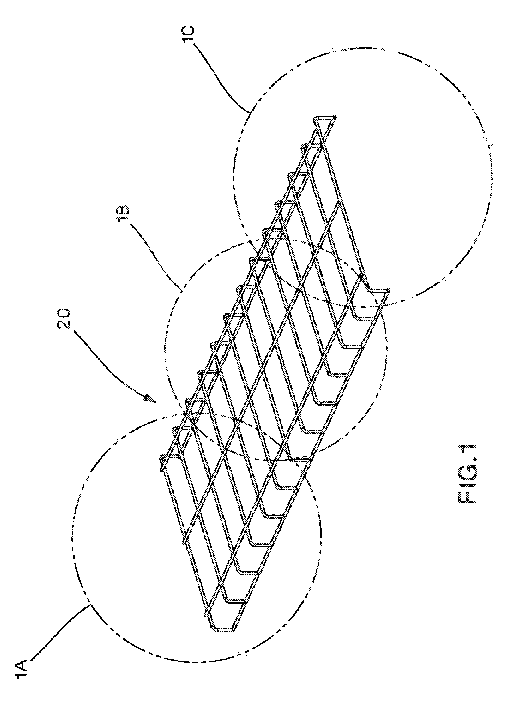
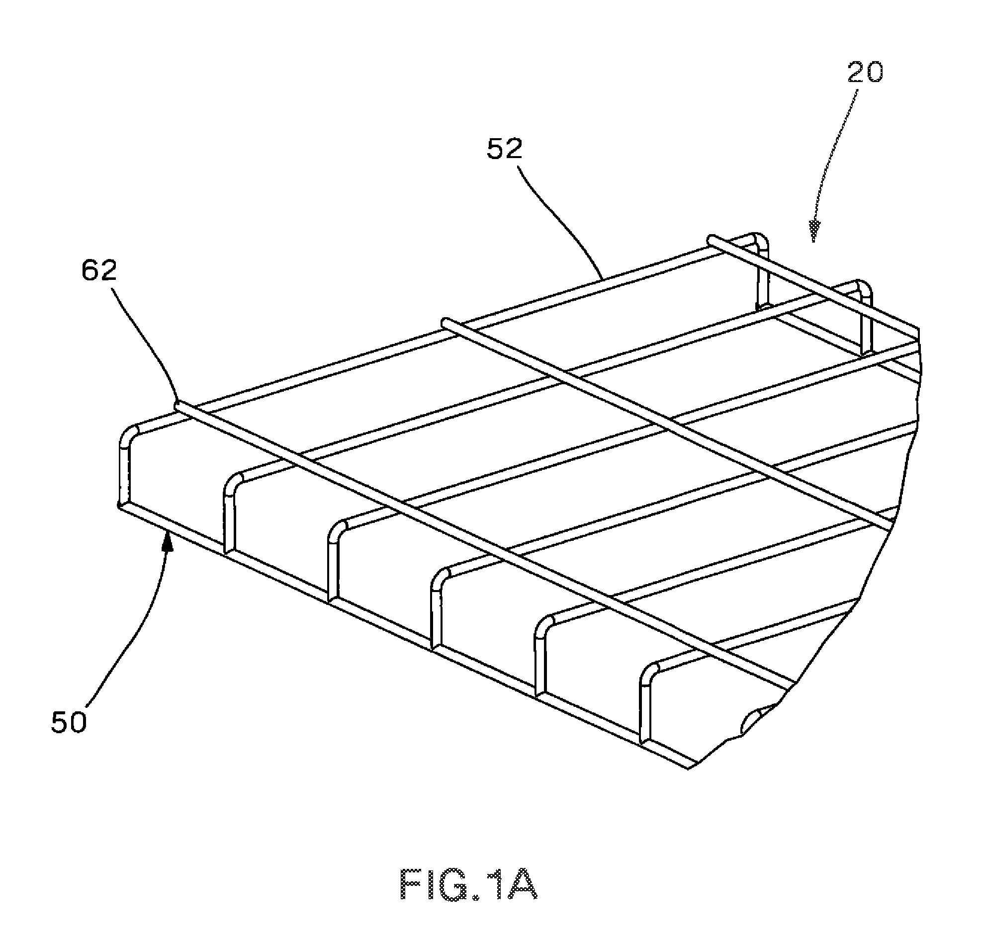
[0050]FIGS. 1-4 illustrate the telescoping wire cable tray system 20 of the present invention. As best seen in FIGS. 1A-C, the telescoping wire cable tray system 20 includes an outer wire cable tray 30 and an inner wire cable tray 50. Each wire cable tray includes a plurality of transverse wires 32, 52 and a plurality of longitudinal wires 42, 62. The transverse wires 32, 52 form a generally flat top 40 for supporting cables routed in the wire cable tray system 20.

[0051]As illustrated in FIG. 4, each transverse wire 32 of the outer wire cable tray 30 includes a top portion 34, side walls portions 36 and bottom portions 38. The outer wire cable tray 30 includes longitudinal wires 42 positioned underneath the top portion 34 of the transverse wires 32. The three longitudinal wires 42 are parallel and are positioned an equal distance apart, and they provide support to the transverse wires 32. A longitudinal wire 42 is also positioned above each bottom portion 38 of the transverse wires ...


PUM


Abstract

The present invention is directed to a telescoping wire cable tray system. The wire cable tray system includes an outer wire cable tray and an inner wire cable tray positioned within the outer wire cable tray. The inner wire cable tray slides or telescopes with respect to the outer wire cable tray enabling the length of the wire cable trays to be adjusted during installation of the wire cable tray system. The wire cable tray system may include trapeze support bars, clamps, side walls or downspout fittings.

Description

CROSS-REFERENCE TO RELATED APPLICATIONS[0001]This application claims priority to U.S. Provisional Application No. 61 / 179,483, filed May 19, 2009 and U.S. Provisional Application No. 61 / 219,433, filed Jun. 23, 2009, the subject matter of which is hereby incorporated by reference in its entirety.BACKGROUND OF THE INVENTION[0002]The present invention relates to a wire cable tray system and, in particular, the invention relates to a telescoping wire cable tray system with adjustable length wire cable trays to accommodate various overhead applications.[0003]Wire cable tray systems are used in data centers and other areas to run cables overhead or below raised floors. Cable tray systems are generally shipped in long sections (e.g., 10 feet) and cut to fit during installation. Cutting and deburring cable trays during installation is very time consuming, and the cut ends can be sharp.[0004]Therefore, there is a need for a cable tray system that allows for adjusting the length of the cable t...

Claims


Application Information

Patent Timeline
IPC IPC(8): A47B23/00F16M13/00
CPCH02G3/0608H02G3/0443
Inventor CAVENEY, JACK E.BROUWER, SHAUN P.NICOLI, ROBERTDAVIS, DAVID R.RAMEY, SAMUEL C.MARRS, SAMUEL M.
Owner PANDUIT
Why Eureka
Try Eureka