Plastic cable bridge-carriage jointing structure

A technology of cable bridge and joint structure, applied in the direction of electrical components, etc., can solve the problems of high installation strength, high cost, poor corrosion resistance, etc., and achieve the effect of convenient installation and disassembly on site, light weight and reasonable structure

Inactive Publication Date: 2007-01-10
王强
View PDF1 Cites 21 Cited by
  • Summary
  • Abstract
  • Description
  • Claims
  • Application Information

AI Technical Summary

Problems solved by technology

Although the installation efficiency can be effectively improved compared with the general bridge frame, on the one hand, due to the use of metal materials, the corro

Method used


Image

  • Plastic cable bridge-carriage jointing structure
  • Plastic cable bridge-carriage jointing structure
  • Plastic cable bridge-carriage jointing structure

Examples


Embodiment 1

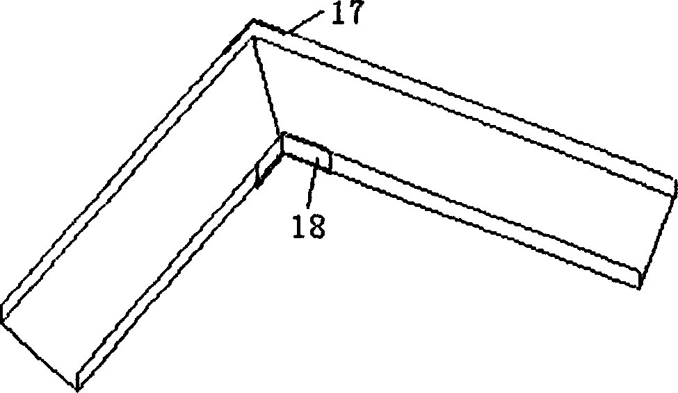
[0013] Example 1: See image 3 , when connecting the connecting ends of plastic cable trays at a certain angle, firstly cut the connecting ends to make them flat butt; then the snap joints are thermally deformed according to the connection angle, and are respectively made to be able to be interlocked with the plastic cable trays The outer curved joint [17] and the inner curved joint [18] are connected; the outer curved joint and the inner curved joint are respectively inserted into the outer curved part and the inner curved part of the joint of the two plastic cable trays , to fasten.

Embodiment 2

[0014] Example 2: see Figure 4 , when the head of the plastic cable tray is processed, the snap joint is thermally deformed according to the section width of the plastic cable tray to form a groove-shaped closed snap joint [19]; ​​the convex strip of the closed snap joint and the plastic cable tray The grooves on the left and right side panels are interlocked.


PUM


Abstract

The invention is related to bridge type joint structure for plastic cable. Left and right side plates in bridge type for plastic cable, and motherboard between left and right side plates are as basic parts to implement connection for bridged plastic cables. Advantages are: novel design, reasonable structure, easy to be assembled or disassembled in site. In addition, besides cascading two bridged plastic cables, the invention also implements connection with corner between two bridged plastic cables, and cap seal head for bridged plastic cables.

Description

technical field [0001] The invention provides a plastic cable bridge joint structure. Background technique [0002] At present, the commonly used cable bridges include metal bridges and glass steel bridges, which are usually connected by bolts. Every two sections of cable bridges need to be connected with ten connecting screws, which makes the installation process cumbersome, labor-intensive for installers, and long construction period. To solve this problem, the usual practice is to use plug-in cable trays to reduce the use of bolts. The utility model patent specification 01249090.3 proposes a plug-in cable tray, which includes a channel-shaped steel frame, and channel-shaped lining plates are fixed inside both ends of the channel-shaped steel frame. When installing, you only need to insert the connecting plate along the channel-shaped steel frame, align the screw holes, and screw in one bolt to fix it. Only two bolts are needed for fixing on both sides. Although the inst...

Claims


Application Information

Patent Timeline
IPC IPC(8): H02G3/06H02G3/04
Inventor 王强
Owner 王强
Why Eureka
Try Eureka