High voltage grounding tool for power maintenance

A power maintenance and high-voltage technology, applied in the direction of conductive connection, electrical component connection, circuit, etc., can solve the problems of equipment operation, heat generation, failure to protect the safety of maintenance personnel, loose wire connecting plates, etc., to improve work efficiency, stable and accurate rotation, Accurate effect of transmission torque

Active Publication Date: 2014-01-22
STATE GRID CORP OF CHINA +1
View PDF11 Cites 39 Cited by
  • Summary
  • Abstract
  • Description
  • Claims
  • Application Information

AI Technical Summary

Problems solved by technology

The high-voltage grounding tools currently used all need to be operated at high altitudes, which are not very convenient to use and operate, and have poor safety performance. The obvious problems of the device are: ①. Its built-in spring compression force is small, the contact resistance between the clamp and the conductor is unqualified, and it cannot protect the safety of the maintenance personnel when a sudden power comes in; ②. When the tightening force is large, it will cause the wire to break. , The wire connecting plate is loose, causing

Method used


Image

  • High voltage grounding tool for power maintenance
  • High voltage grounding tool for power maintenance

Examples


Embodiment 1

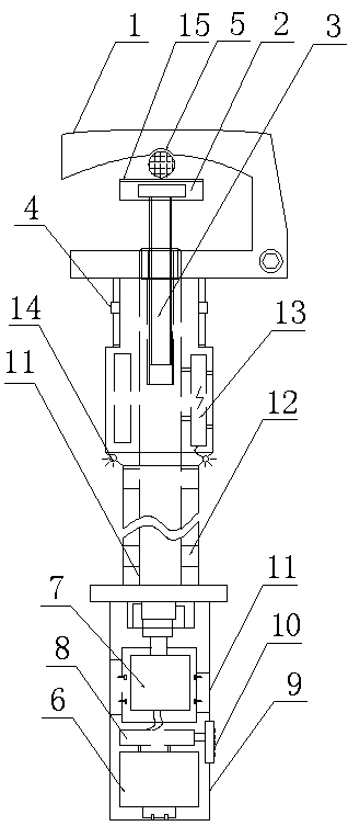
[0020] Such as figure 1 As shown, a high-voltage grounding tool for electric maintenance includes a grounding wire chuck and an operating rod 9, the wire chuck includes a C-shaped hitch 1, a wire clamping piece 2 and a lifting rod 3, and the operating rod 9 The top is provided with a joint 4 connected to the C-shaped hitch 1 , the upper end of the elevating rod 3 is connected to the wire clamping piece 2 with a protective layer 15 , and the operating rod 9 has a built-in drive mechanism connected to the elevating rod 3 .

[0021] The inner side of the upper part of the C-shaped hitch 1 is set as an upward concave arc structure, and the highest point is set with a wire clamping groove 5 .

[0022] The drive mechanism includes a power supply 6, a motor 7, a control circuit 8 and a transmission member, the motor 7 is embedded in the operating lever 9, and an operation panel 10 connected to the control circuit 8 is arranged outside the operating lever 9, and the transmission membe...

Embodiment 2

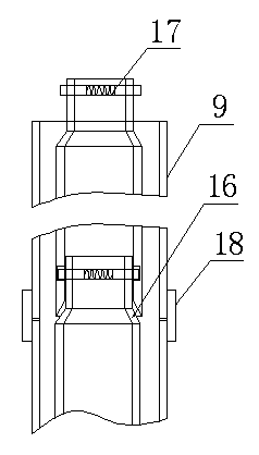
[0027] Such as figure 2 As shown, the difference from Embodiment 1 is that: the operating rod 9 is set as a multi-stage plug-in type, the locking ring 18 is arranged between the 9 segments of the operating rod, the reducing tube 16 is arranged between the segments of the movable sleeve 11, and the reducing tube 16 is arranged between the segments. An elastic pin 17 or a key structure cooperating with the movable sleeve 11 is arranged on the diameter pipe 16 .

[0028]The wire collet of the present invention includes a C-shaped hook frame, a wire clamp moving piece and a lifting rod, through which the C-shaped hitching frame is conveniently hung on the wire, and the lifting rod is used to push the wire clamping moving piece to move Realize the clamping of wires, prevent safety accidents caused by unreliable grounding, and improve the safety of operators. The lifting rod is driven by the driving mechanism built in the operating rod, which can well realize safe operation at low ...


PUM


Abstract

The invention discloses a high voltage grounding tool for power maintenance, which comprises a grounding wire chuck and an operating rod, wherein the wire chuck comprises a C-shaped hanging frame, a wire clamp moving plate and a lifting rod; a connector connected with the C-shaped hanging frame is arranged at the top of the operating rod; the upper end of the lifting rod is connected with the wire clamp moving plate; a driving mechanism connected with the lifting rod is arranged in the operating rod; the operating rod is arranged in a multi-section insertion manner; locking rings are arranged among sections of the operating rod; reducer pipes are arranged among sections of a movable casing pipe; elastic pins or key structures matched with the movable casing pipe are arranged on the reducer pipes. According to the invention, the high voltage grounding tool is hung on a wire by utilizing the C-shaped hanging frame; the wire is clamped by adopting the lifting rod; the wire-off accident is prevented; the low-position safe operation is realized; the potential safety hazard caused by the climbing operation is avoided; the working difficulty is reduced; the working efficiency is improved; the sectional design concept is adopted; the flexible variation of the length of the operating rod is ensured; in the transmission link, the interchangeable connection can be carried out; the effects are obvious.

Description

technical field [0001] The invention belongs to the technical field of safety tools, in particular to a high-voltage grounding tool for electric power maintenance. Background technique [0002] The high-voltage grounding tool is one of the safety tools commonly used in the maintenance of high-voltage lines. It is used to temporarily connect the power supply to the ground to prevent the power line from being powered off due to misoperation and other reasons. The high-voltage grounding tools currently used all need to be operated at high altitudes, which are not very convenient to use and operate, and have poor safety performance. The obvious problems of the device are: ①. Its built-in spring compression force is small, the contact resistance between the clamp and the conductor is unqualified, and it cannot protect the safety of the maintenance personnel when a sudden power comes in; ②. When the tightening force is large, it will cause the wire to break. 1. The wire connectin...

Claims


Application Information

Patent Timeline
IPC IPC(8): H01R11/14H01R43/00H02G1/02
CPCH01R11/11H02G1/02
Inventor 张亮智全中陈宏伟文凯曹建奎
Owner STATE GRID CORP OF CHINA
Why Eureka
Try Eureka