Case cable organizer structure

a cable organizer and organizer technology, applied in the direction of electrical apparatus casings/cabinets/drawers, electrical apparatus construction details, instruments, etc., can solve problems such as friction-induced noise, jamming or seized support frames, and poor design, and achieve the effect of solving problems such as noise, noise, and nois

Inactive Publication Date: 2015-11-26
NAN JUEN INT CO LTD
View PDF3 Cites 28 Cited by
  • Summary
  • Abstract
  • Description
  • Claims
  • Application Information

AI Technical Summary

Benefits of technology

[0007]The present disclosure is to provide a case cable organizer structure featuring simplicity, steady and smooth running, and economic effect as well as operation quality in manufacture and utility.

Problems solved by technology

The conventional cable organizer which satisfies supporting and operating functions still has some drawbacks, for example, the cable organizer with a linear main body laterally stretching and a support frame deflecting for movement performs an asymmetric deflective motion, which makes the support frame jammed or seized or friction-induced noise in the course of an asymmetric drag, and is not a good design.
Therefore, how to solve these problems is an important issue confronted by the persons skilled in the art.

Method used


Image

  • Case cable organizer structure
  • Case cable organizer structure
  • Case cable organizer structure

Examples


Embodiment Construction

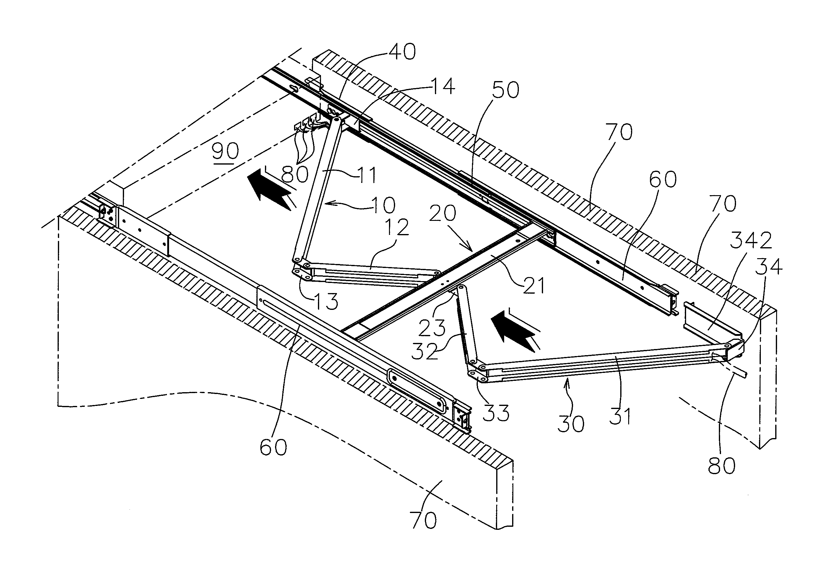
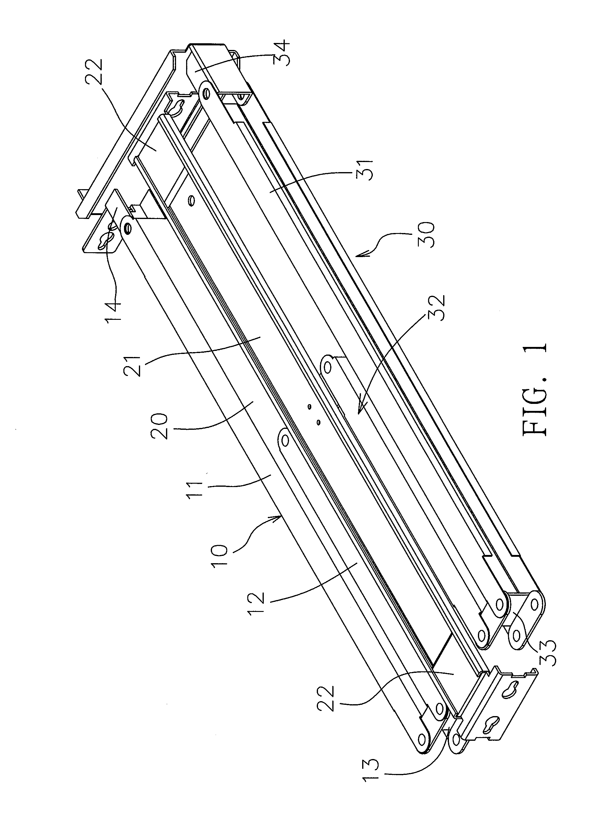
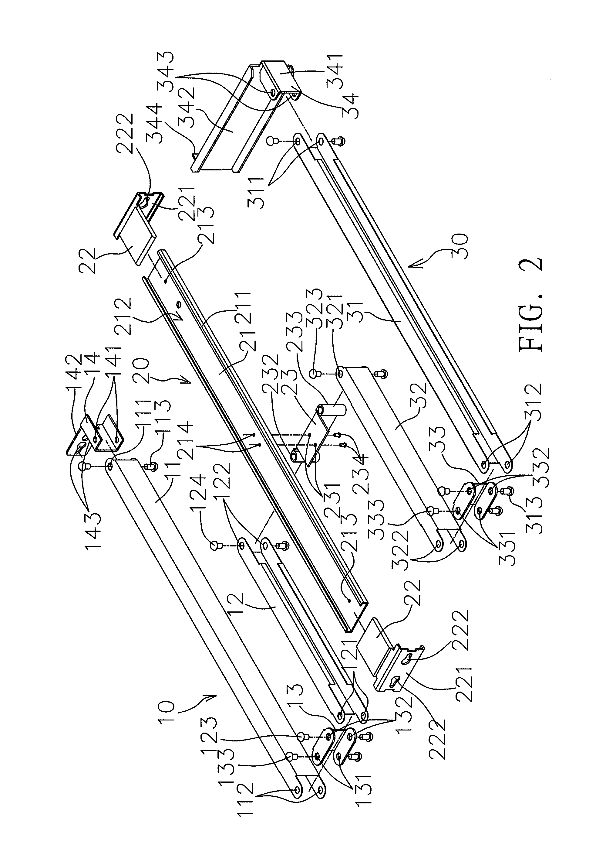
[0023]Please refer to FIGS. 1 and 2 which illustrate a case cable organizer in the present disclosure comprises a front cable tray unit 10, a shifting device 20 and a rear cable tray unit 30. The front cable tray unit 10 comprises a first front cable tray 11 and a second front cable tray 12, both of which are pivoted on each other. The first front cable tray 11 and the second front cable tray 12 are U-shaped tubular frames in which wiring spaces are designed for accommodation of a cable 80 (FIG. 5). The first front cable tray 11 has track's pin-jointed ends 111 at one side and tray's pin-jointed ends 112 at the other end wherein the track's pin jointed ends 111 are pivoted on an inner-track pin joint 14, which has two pin-jointed ends 141 positioned to the track's pin-jointed ends 111 by rivet pins 113, for pivoted on the first front cable tray 11 and the inner-track pin joint 14. The inner-track pin joint 14 develops a forward protruding locator 142 on which pilot holes 143 are dri...


PUM


Abstract

A case cable organizer structure, comprising: a front cable tray unit comprising a first front cable tray and a second front cable tray which is pivoted on and stays behind the first front cable tray and has board's pin-jointed ends at one side; a central shifting board which is arranged behind the second front cable tray and provided with pin-jointed parts securely fixed at central front and rear sides wherein the pin-jointed part at the front side is pivoted on board's pin-jointed ends of the second front cable tray; a rear cable tray unit comprising a first rear cable tray and a second rear cable tray which is pivoted on the first rear cable and is arranged in the front of the first rear cable tray and has board's pin-jointed ends at one side wherein the board's pin-jointed ends are pivoted on a pin-jointed part at the rear end of the central shifting board.

Description

BACKGROUND OF THE INVENTION[0001]1. Field of the Invention[0002]The present disclosure relates to a case cable organizer, particularly a case cable organizer structure which is easily manufactured and features simplified components for stabilized operation.[0003]2. Description of the Related Art[0004]The existing mainframe computer / electronic equipment system is usually held and stacked in a cabinet which is internally provided with slide tracks at both sides for easily assembling or maintaining computers / electronic devices (e.g., servers). In this context, the complex cables connected to back sides of computers / electronic devices should be accommodated and held in cable organizers for no cable getting tangled or falling off in the course of moving cases of computers / electronic devices. As disclosed in U.S. Pat. No. 1,336,229, a conventional cable organizer comprises a cable tray body, a support frame, a support slipper, a support fastener, and two mounting elements: the cable tray ...

Claims


Application Information

Patent Timeline
Patent Type & Authority Applications(United States)
IPC IPC(8): H05K7/18
CPCH05K7/18H05K7/1491
Inventor CHANG, FU-TIEN
Owner NAN JUEN INT CO LTD
Why Eureka
Try Eureka