Cable laying device

A cable laying and cable reel technology, which is applied in the directions of cable laying equipment, transportation and packaging, thin material handling, etc., can solve the problems of cable changing from the guide groove, cable hanging on foreign objects, loss, etc., so as to reduce labor intensity and The effect of small friction and simple operation

Active Publication Date: 2015-05-13
STATE GRID CORP OF CHINA +2
View PDF4 Cites 27 Cited by
  • Summary
  • Abstract
  • Description
  • Claims
  • Application Information

AI Technical Summary

Problems solved by technology

When the cable is drawn out from the cable reel for laying, sometimes the cable will change its direction and break away from the guide groove du

Method used


Image

  • Cable laying device
  • Cable laying device
  • Cable laying device

Examples


Embodiment Construction

[0016] The technical solution of this patent will be further described in detail below in conjunction with specific embodiments.

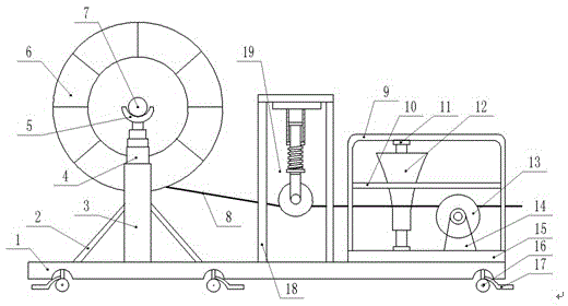
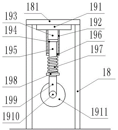
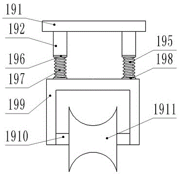
[0017] see Figure 1-4 , a cable laying device, comprising a base 1, a cable reel 6, a cable 8, a fixed frame 9, a guide bracket 18 and a third pulley 12; both sides below the base 1 are equipped with three sets of universal wheels 16, Brake pads 17 are provided on the wheel 16, and the brake pads 17 can limit the movement of the universal wheel 16. Two support columns 3 are symmetrically arranged above the left end of the base 1, and the outer walls of the support column 3 are fixed with supports. Frame 2, the support frame 2 makes the support column 3 more stable, the upper end of the support column 3 is fixed with a hydraulic jack 4, and the top of the hydraulic jack 4 is fixed with a support groove 5, and the support groove 5 is arc-shaped. A rotating shaft 7 is erected between the 5, wherein the cable reel 6 is set in the support groove 5 thr...


PUM


Abstract

The invention discloses a cable laying device. The cable laying device comprises a base, cable trays, a cable, a fixing frame, a guide support and a third pulley; three groups of universal wheels are distributed on each side below the base; two supporting columns are symmetrically arranged above the bilateral sides of the left end of the base respectively; supporting frames are fixedly arranged on the bilateral sides of the outer wall of each supporting column respectively; a hydraulic jack is fixedly arranged at the upper end of each supporting column; a supporting groove which is in a circular arc shape is fixedly formed above each hydraulic jack; a rotating shaft is arranged between the two supporting grooves in a straddled mode; the cable trays are arranged in the supporting grooves through the rotating shaft respectively; the upper end of the guide support is provided with a beam; an elastic guide device is fixed in the middle of the bottom surface of the beam; an elastic guide base, a first guide wheel and a spring are arranged in the elastic guide device. According to the cable laying device, the operation is simple, the use is convenient, the height of each cable supporting frame can be adjusted, the friction force in the movement process of the cable is reduced due to a pulley group, and accordingly the labor intensity of the construction personnel is reduced.

Description

technical field [0001] The invention relates to power equipment, in particular to a cable laying device. Background technique [0002] At present, cables are used more and more in power system lines. Most cables are packaged in cable reels. During cable laying construction, the cable reels need to be supported according to the site construction conditions to facilitate cable laying. Convenient, according to the change of the cable laying path, the installation point of the cable tray will be changed again. When the cable reel is large or heavy, the movement of the cable reel will be quite troublesome, which virtually prolongs the construction period. When the cable is drawn out from the cable reel for laying, sometimes the cable will change its direction and break away from the guide groove due to the change of the traction angle, and even the cable will hang on foreign objects and cause its own damage, which brings unnecessary losses. Contents of the invention [00...

Claims


Application Information

Patent Timeline
IPC IPC(8): H02G1/06B65H49/18B65H49/22B65H57/14B65H57/26
Inventor 张思陈颖杨东方施勇刘新
Owner STATE GRID CORP OF CHINA
Why Eureka
Try Eureka