Method to correct the B1 field in MR measurements and MR apparatus for implementing the method

a radiofrequency pulse and field strength technology, applied in the field of method to correct the field strength of radiofrequency pulses, can solve the problems of falsifying the measurement, changing the antenna load, and unintentional changes in the received magnetic resonance signal

Active Publication Date: 2005-08-09
SIEMENS HEALTHCARE GMBH
View PDF7 Cites 9 Cited by
  • Summary
  • Abstract
  • Description
  • Claims
  • Application Information

AI Technical Summary

Benefits of technology

The technical effect of this patent is that it provides a way for holding the intensity of the radio-frequency pulses (B1) stable during a medical imaging session, without requiring any adjustments or extra steps. This helps ensure consistent results across different patients and improves the accuracy of the data collected from the MRI machine.

Problems solved by technology

The technical problem addressed in this patent text relates to the issue of unwanted changes in the measured magnetic resonance signals caused by variations in the surrounding environment, particularly related to the position of the examinee's body relative to the transmitter antennas used during the scan. These variations require frequent re-adjustment of the transmitting power to ensure accurate results, leading to increased difficulty in achieving efficient and high-quality MRI scans when conducting multiple examinations.

Method used


Image

  • Method to correct the B1 field in MR measurements and MR apparatus for implementing the method
  • Method to correct the B1 field in MR measurements and MR apparatus for implementing the method
  • Method to correct the B1 field in MR measurements and MR apparatus for implementing the method

Examples


Embodiment Construction

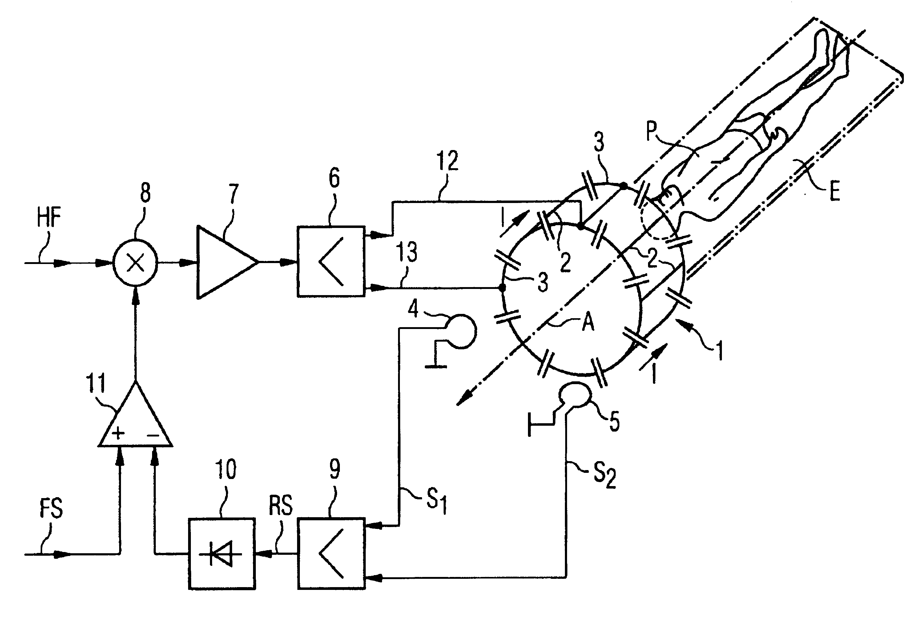
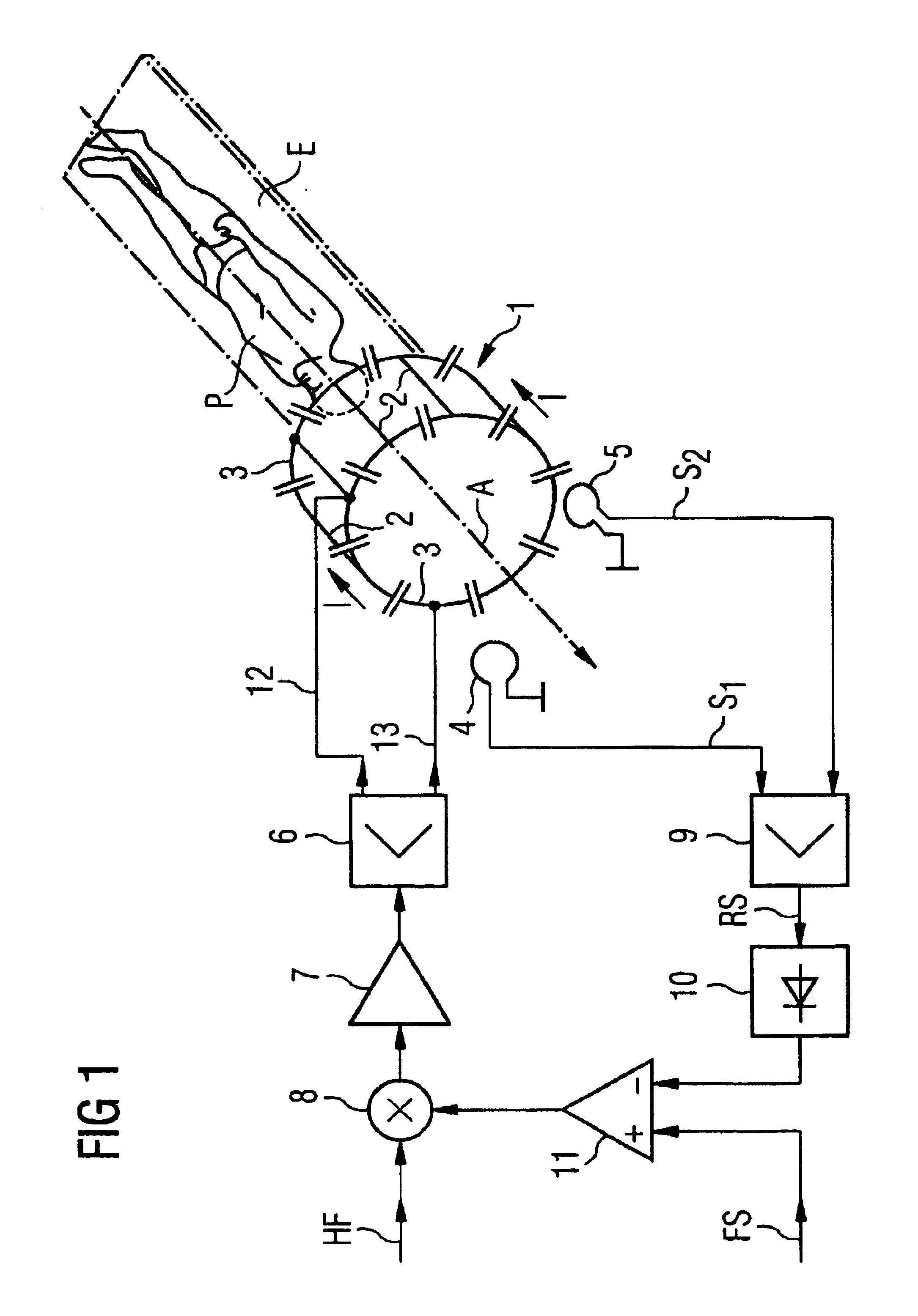
[0023]In all exemplary embodiments, it is assumed that the antenna 1 is a transmission antenna 1 of a type known as a “birdcage antenna”, typically used in magnetic resonance examination devices. These antenna 1 is assembled so as to resemble a birdcage and has a cylindrical shape with two end rings 3 at the ends and longitudinal rods 2 proceeding in parallel between the end rings 3. Capacitive elements are connected in the end rings 3 between the rods 2. With such an antenna 1, relatively homogenous circular polarized B1 fields proceeding transverse to the cylinder axis A of the antenna 1 can be generated.

[0024]During an examination, a patient P is positioned along the cylinder axis A of the antenna 1 in the internal chamber of the antenna 1. The position of the patient P along the cylinder axis A can be changed between two individual exposures, in order to examine different body regions of the patient P. For this, the patient P is typically located on an examination bed (not shown...


PUM


Abstract

In a method and magnetic resonance examination apparatus wherein the field strength of radio-frequency pulses emitted by an antenna of the magnetic apparatus, the current flowing in the antenna upon the emission of the radio-frequency pulses is regulated by a predetermined nominal value by variation of a power fed into the antenna.

Description


Claims


Application Information

Patent Timeline
Owner SIEMENS HEALTHCARE GMBH
Why Eureka
Try Eureka