Candle holder adapter for an electric lighting fixture

a technology for adapters and lighting fixtures, applied in portable electric lighting, light fastenings, light fixtures, etc., can solve the problems of high manufacturing cost, inability to capture the charm of natural flames, and bulky appearan

Inactive Publication Date: 2005-08-16
LOGAN JAMES D +1
View PDF6 Cites 17 Cited by
  • Summary
  • Abstract
  • Description
  • Claims
  • Application Information

AI Technical Summary

Benefits of technology

[0011]The invention enables a homeowner who is entertaining to replace the light bulbs in a electric chandelier with real candles. In this way, the homeowner may enjoy the convenience of electric lighting from such a fixture but, on special occasions, use that same fixture to provide candlelight.

Problems solved by technology

While these “candelabra” fixtures are popular, they fail to totally capture the charm provided by the warm glow of a natural flame.
Candle holding adapters of this kind are described in U.S. Pat. No. 3,855,464 issued to S. J. Angelo entitled “Electric Light-to-Candle Converter” and in U.S. Pat. No. 5,482,456 issued to J. M. and R. E. Jwayad entitled “Light Fixture Candle Adapter.” Although both of these adapters allow candles to be used in light fixtures, they are expensive to manufacture and appear bulky when mounted on top of the socket support column commonly used in electric candelabras.

Method used


Image

  • Candle holder adapter for an electric lighting fixture
  • Candle holder adapter for an electric lighting fixture
  • Candle holder adapter for an electric lighting fixture

Examples


Embodiment Construction

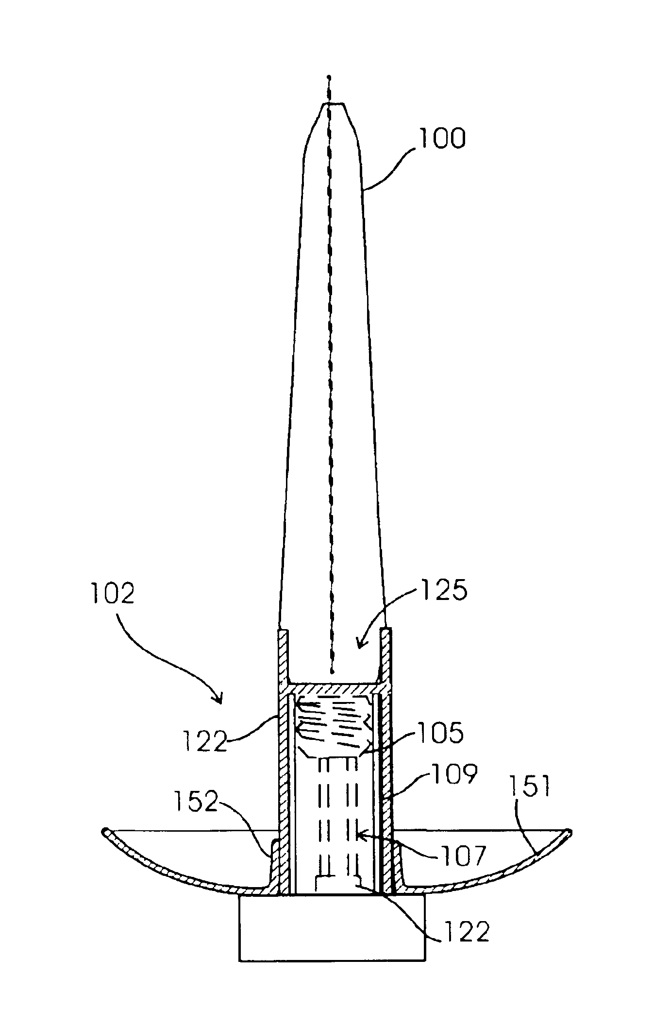
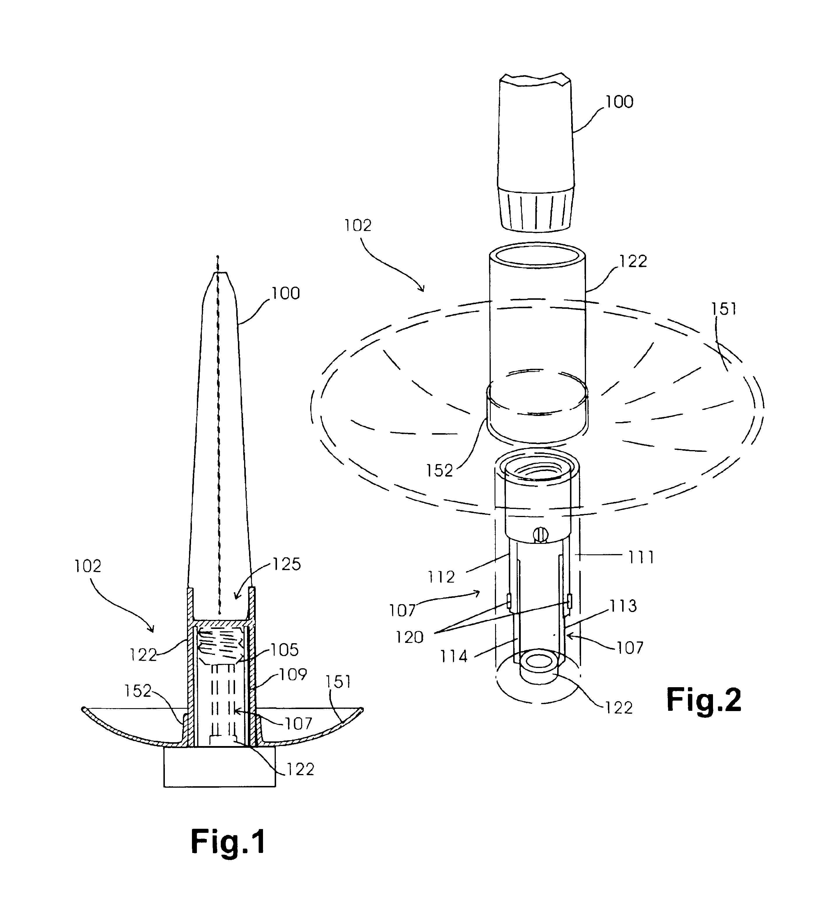
[0020]The present invention permits candles to used with an existing electrical fixture. A first illustrative embodiment of the invention is shown in FIGS. 1 and 2 and comprises a taper candle 100 that is inserted into and retained by a candle holder adapter indicated generally at 102. The candle 100 and the candle holder adapter 102 replace the electric light bulb (not shown) that is normally screwed into a socket 105 at the top of an upright socket support structure indicated generally at 107 which is surrounded by a decorative sleeve 109.

[0021]Most electric lamp chandeliers use candle-like bulbs having a standard threaded “candelabra base” held by a standard socket assembly of the kind shown at 105 and 107 inFIGS. 1 and 2. The bulb screws into the female threaded electrical socket 105 mounted at the top of an upright support structure 107 consisting of two downwardly extending channels 111 and 112 which receive the two upwardly extending prongs 113 and 114 respectively of a base ...


PUM


Abstract

An adapter for converting an electric light fixture into a candle-burning chandelier. A candle holder adapter includes a cavity at the bottom which fits over and is retained by the vertical light bulb socket support. The candle holder may include an wax catching tray. The candle may be a conventional candle which fits into the candle holder adapter, or may be specially formed to mate with the adapter. The adapter may hold or form a liquid fuel reservior for a fuel burning candle. In an O.E.M. fixture, the vertical light bulb socket support may be removed from the fixture and replaced by a conventional candle or a specially formed candle holder.

Description

FIELD OF THE INVENTION[0001]This invention relates to decorative candles and candle holders.BACKGROUND OF THE INVENTION[0002]With the introduction of the light bulb in 1879, the use of candles and oil burning lamps declined until more recently when a renewed popularity for candles and oil lamps occurred. No longer man's major source of light, candles and oil lamps continue to grow in popularity and use. Today, the natural flame of candles and oil lamps has come symbolize celebration, mark romance, define ceremony, and accent decor.[0003]To mimic the charm of candles and oil lamps, electric lamps have been developed having low output bulbs shaped and sized to resemble candle flames. A common lighting fixture includes a tall cylindrical sleeve shaped like the body of a candle. A small electric bulb with a pointed top, generally in the shape of a flame, screws into the top of sleeve. These bulbs typically have a smaller “candelabra” socket and are widely used in decorative lamp fixture...

Claims


Application Information

Patent Timeline
Patent Type & Authority Patents(United States)
IPC IPC(8): F21L19/00F21V35/00
CPCF21V35/003
Inventor LOGAN, JAMES D.THORNBURGH, CAREN
Owner LOGAN JAMES D
Why Eureka
Try Eureka