Spinal implant, driver tool and nut guide

a technology for spinal implants and driver tools, applied in the field of spinal implants, can solve the problems of unstable fixation of spinal implants, unfavorable treatment of spinal implants,

Inactive Publication Date: 2005-08-23
SHOWA IKA KOHGYO
View PDF35 Cites 81 Cited by
  • Summary
  • Abstract
  • Description
  • Claims
  • Application Information

AI Technical Summary

Benefits of technology

[0010]According to a third aspect of the present invention, there is provided a nut guide for guiding a nut member of a spinal implant having an implant body and an anchoring screw section, and for guiding a driver tool having a lower end formed with a nut engagement tip, wherein a vertebral connecting rod is retained with a pair of the spinal implant to be anchored into vertebral bodies. The nut guide comprises a grip section, and a hollow cylindrical shaft extending from the grip section and adapted to permit insertion of the driver tool therein,

Problems solved by technology

During this operating step, there exist some difficulties in precisely adjusting the orientation of the U-shaped recesses of the spaced spinal implants anchored in vertebral bodies, angulation of the spinal implants and depth of the spinal implants, with a resultant undesirable fixation of the implants and the connecting rod.
Accordingly, after the spinal implant penetrates in the vertebral body, fixation of the spinal implant is unstable and is liable to be undesirably affected with external forces when they are applied to the spinal implants.
In this prior art, each of the pedicle screws is composed of the same solid material as in the prior art discussed above, and a diffi

Method used


Image

  • Spinal implant, driver tool and nut guide
  • Spinal implant, driver tool and nut guide
  • Spinal implant, driver tool and nut guide

Examples


Embodiment Construction

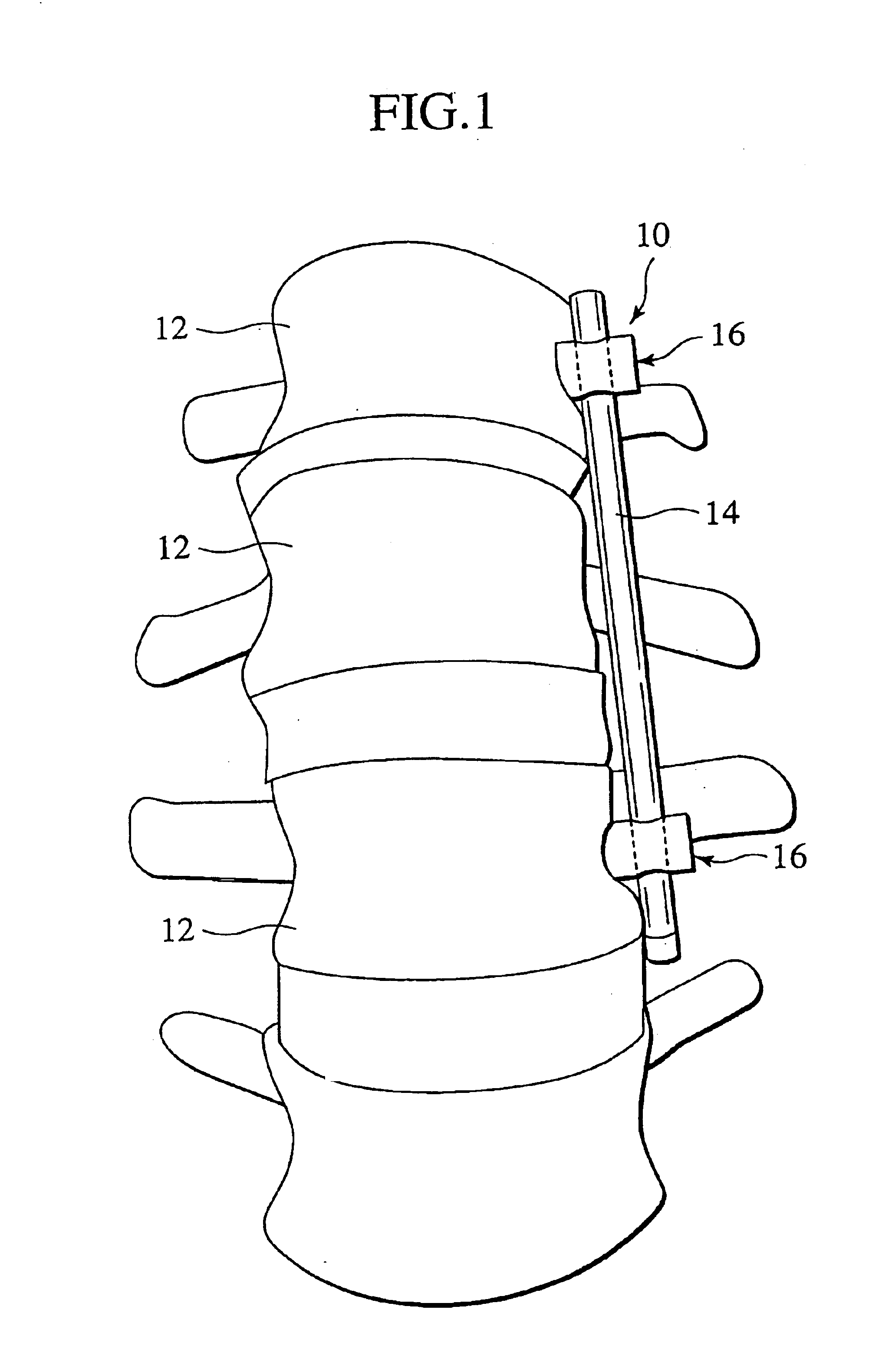
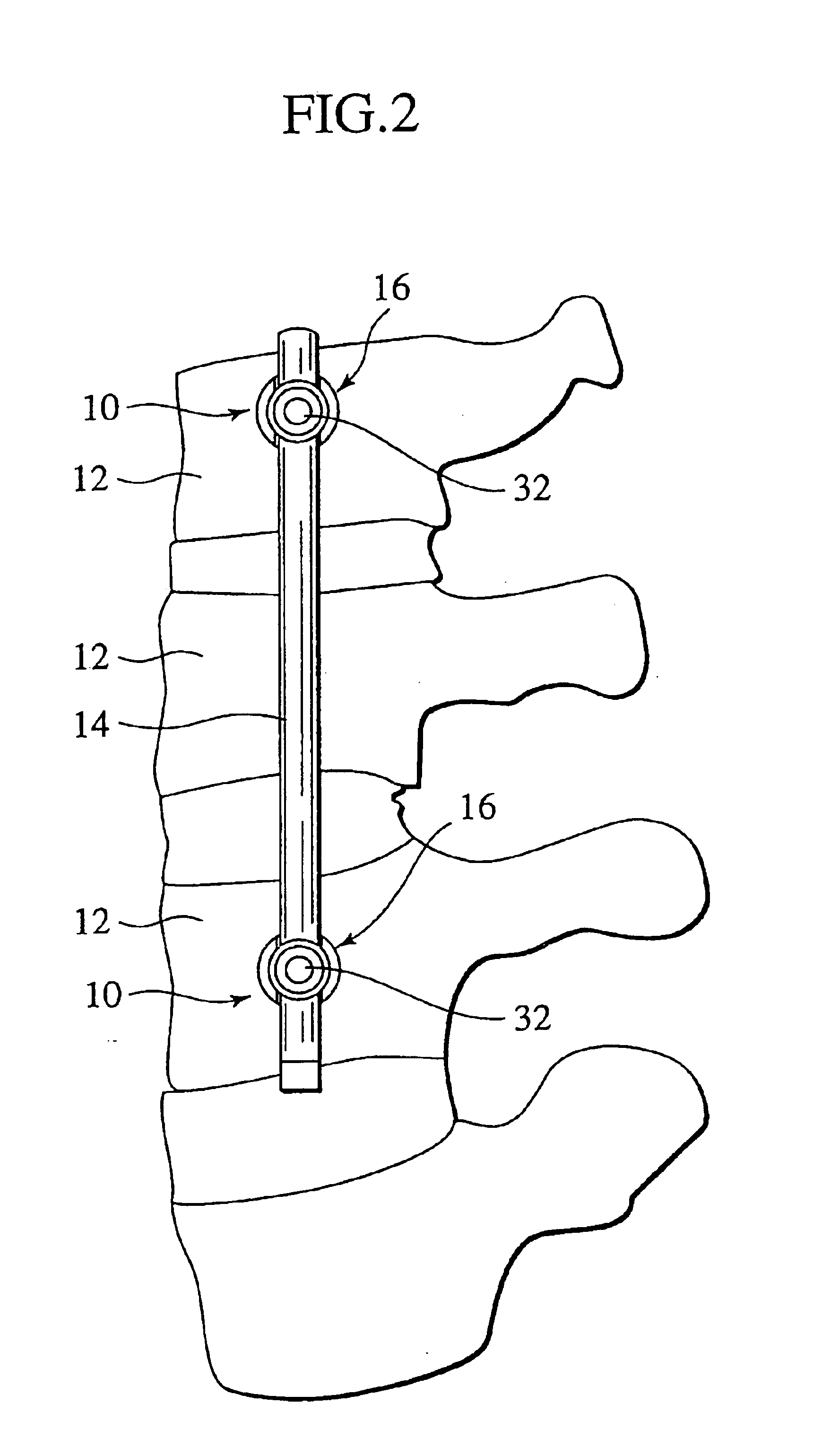
[0028]Referring to the drawings and more particularly to FIGS. 1 and 2, a spinal osteosynthesis device, generally designated at 10, is shown as applied to separate vertebral bodies 12 for interconnecting plural vertebral bodies 12 in place.

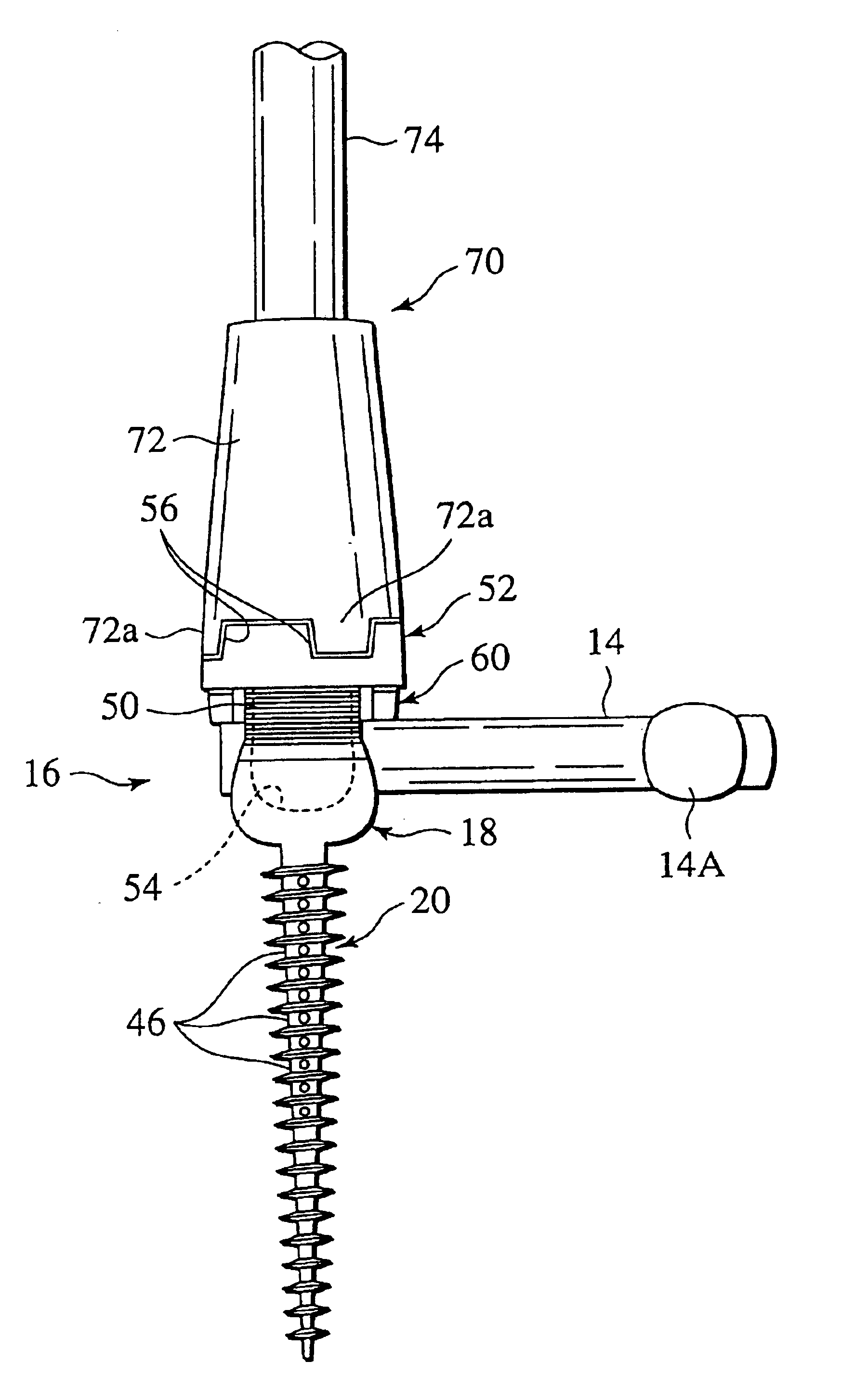
[0029]The spinal osteosynthesis device 10 includes an elongated vertebral connecting rod 14 retained by a pair of spinal implants 16 of a first preferred embodiment according to the present invention. Each of the spinal implants 16 penetrates each vertebral body 12 in a manner as will be discussed below in detail. The connecting rod 14 is made of malleable, elastically deformable material having a large elastic capacity, permitting elastic deformation necessary for adaptation it to differences in alignment, angulation and depth of penetration of the implants 16.

[0030]Referring now to FIGS. 3 and 4, the spinal implant 16 includes a cylindrical implant body 18 for firmly retaining the connecting rod 14 in place, and an anchoring screw section 20 tha...


PUM


Abstract

A driver tool for a spinal implant having an implant body and an anchoring screw portion, and a nut member screwed onto a head portion of the implant body and having an upper wall formed with a tool engagement groov. The driver tool includes an elongated shaft, and a tubular tool end having substantially the same diameter as that of the nut member. The tubular tool end has an engaging segment engageable with the engagement groove formed on the upper wall of the nut member.

Description

[0001]This is a division of application Ser. No. 09 / 818,229, filed Mar. 27, 2001, now U.S. Pat. No. 6,488,682 the contents of which are expressly incorporated by reference herein in its entirety.BACKGROUND OF THE INVENTION[0002]The present invention relates to spinal implants for osteosynthesis devices and, more particularly, to a spinal implant, a driver tool specifically suited for the spinal implant, and a nut guide suited for the spinal implant.[0003]In recent years, various research and development have been attempted to provide a spinal implant that is designed to achieve adaptation to differences in alignment, augulation and depth of penetration of adjacent spinal implants anchored to vertebral bodies which are spaced from one another.[0004]One of such implants is disclosed in U.S. Pat. No. 5,154,719. This device includes a head portion having a pair of upright branches which are internally threaded and which has a U-shaped recess, and a screw portion projecting from the head...

Claims


Application Information

Patent Timeline
IPC IPC(8): A61B17/70A61B17/88A61F2/44
CPCA61B17/7005A61B17/7032A61B17/7091A61B17/864A61B2017/90A61B17/90A61F2/44
Inventor ORIBE, KAZUYATAKAMIDO, HIROSHI
Owner SHOWA IKA KOHGYO
Why Eureka
Try Eureka