Endoprosthesis with intermediate part

Inactive Publication Date: 2007-07-26
LINK AMERICA INC
View PDF7 Cites 26 Cited by
  • Summary
  • Abstract
  • Description
  • Claims
  • Application Information

AI Technical Summary

Benefits of technology

[0005] Starting out from the cited prior art, the object of the invention is to improve an endoprosthesis of the type mentioned

Problems solved by technology

The latter is therefore subject to substantial loading.
In practice it has been found that substantial loads can result in a “warping” of the intermediate part normally made of polyethylene.
There is therefore a danger that, under increased loads, as may occur for example as a

Method used


Image

  • Endoprosthesis with intermediate part
  • Endoprosthesis with intermediate part
  • Endoprosthesis with intermediate part

Examples


Embodiment Construction

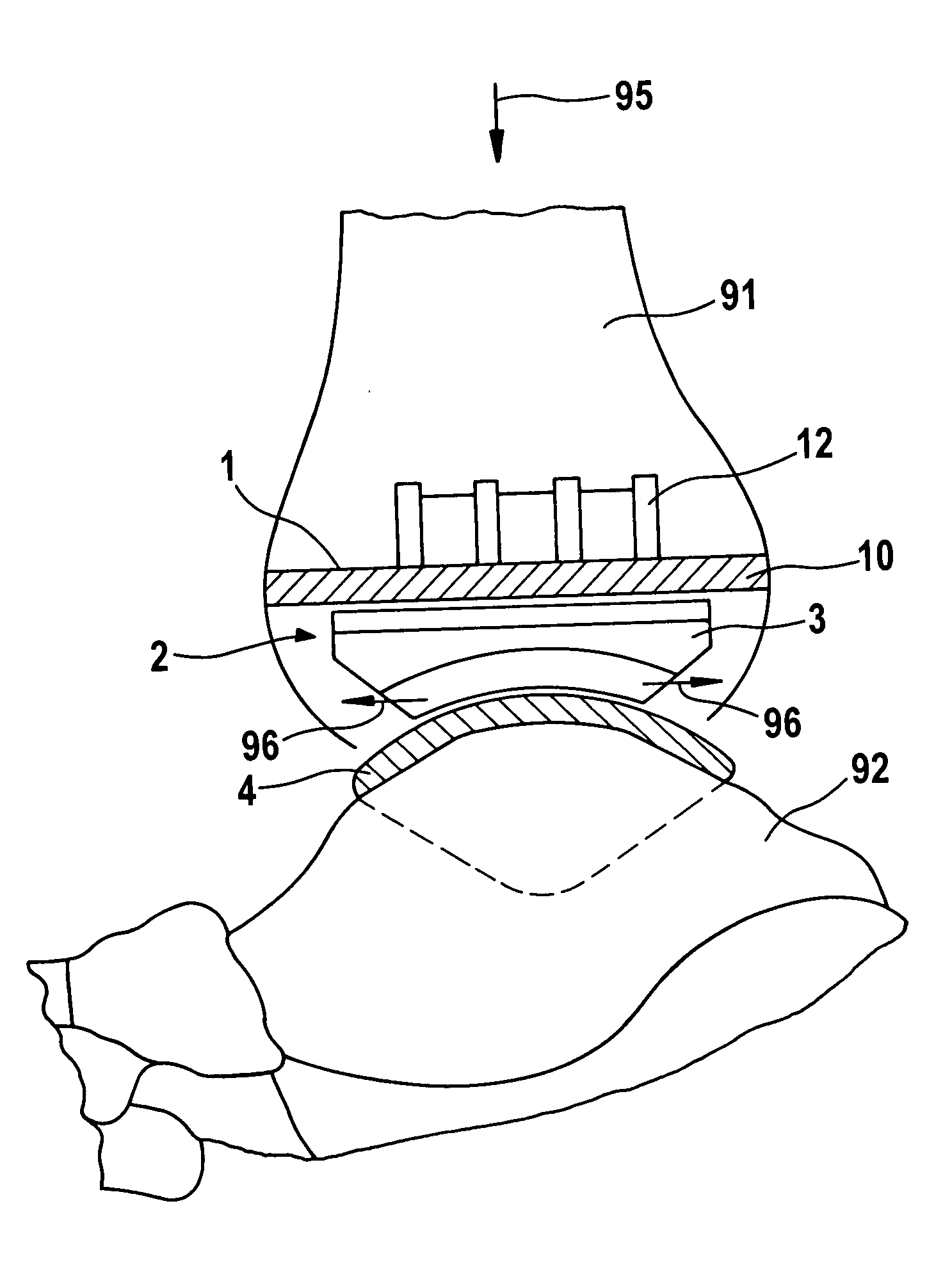
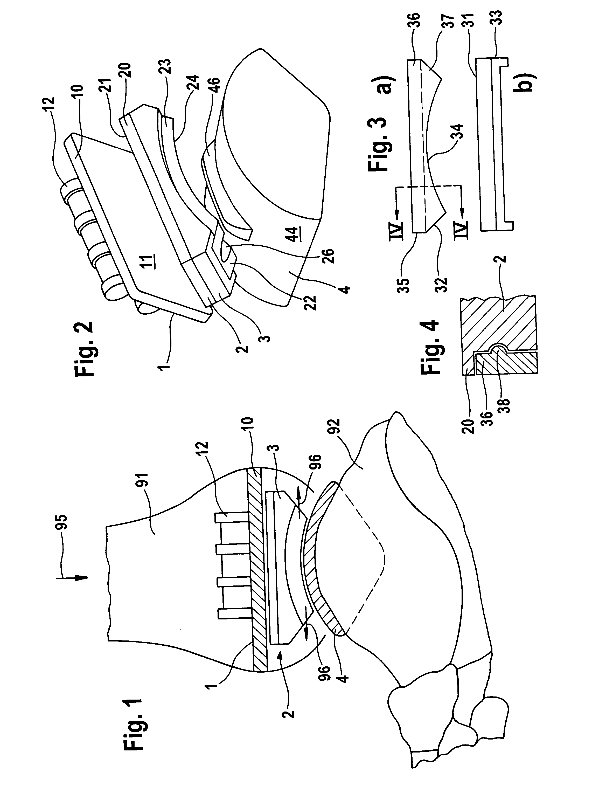
[0030] The depicted illustrative embodiment of the prosthesis according to the invention is an ankle joint prosthesis. It will be noted that the invention can also be applied to other types of endoprostheses, for example intervertebral endoprostheses. The important point is that the endoprosthesis has two bearings whose planes of movement are defined by the slide surfaces having different contours.

[0031] The endoprosthesis according to the depicted illustrative embodiment basically comprises three components. The first component is a shin bone component 1 designed to be arranged on the lower end of a tibia 91. It has a plate-shaped part 10 whose bottom forms a plane slide surface 11. On the top of the plate-shaped part 10 there is an anchoring body 12 which is provided with projections and which serves to secure the shin bone component 1 in corresponding resection depressions in the tibia 91.

[0032] The prosthesis further comprises an ankle bone component 4. It has a saddle-like co...


PUM

PropertyMeasurementUnit
Distanceaaaaaaaaaa
Distanceaaaaaaaaaa
Lengthaaaaaaaaaa

Abstract

The invention relates to an endoprosthesis for replacement of a joint, 2 slide surfaces having different contours and correspondingly determining movement planes for in each case 1 bearing being formed by an intermediate part 2. Provision is made according to the invention for a clamping bracket to enclose the slide surfaces of the intermediate part and to be arranged thereon such that it is arranged free from the movement planes defined by the slide surfaces having different contours. It is thus also possible to strengthen endopreostheses which have complex biomechanics having a plurality of degrees of freedom.

Description

REFERENCE TO RELATED APPLICATIONS [0001] This application claims the priority of U.S. Provisional Application Ser. Nos. 60 / 749,103, filed Dec. 12, 2005, and 60 / 755,079, filed Jan. 3, 2006, the contents of both of which prior applications are incorporated herein by reference.FIELD OF THE INVENTION [0002] The invention relates to an endoprosthesis for replacement of a joint, comprising a component which is to be connected to a lower bone and which has a top slide surface, a component which is to be connected to an upper bone and which has a bottom slide surface, and an intermediate part which, on its bottom and top, has in each case a matching slide surface which, together with the slide surfaces of the aforementioned components, in each case forms a bearing. BACKGROUND OF THE INVENTION [0003] Endoprostheses of this kind are used, for example, for replacement of the ankle joint (FR-A 2 676 917, WO-A-03 / 075802, WO-A-2005 / 030098). In these, the components and the intermediate part coope...

Claims


Application Information

Patent Timeline
IPC IPC(8): A61F2/30
CPCA61F2/38A61F2310/00796A61F2/4425A61F2002/30224A61F2002/30331A61F2002/3039A61F2002/30884A61F2002/4205A61F2002/4207A61F2220/0025A61F2220/0033A61F2230/0069A61F2310/00023A61F2310/00029A61F2/4202A61F2/42A61F2/44
Inventor KELLER, ARNOLDKOFOED, HAKON
Owner LINK AMERICA INC
Why Eureka
Try Eureka