Apparatus for connecting a fiber optic or rigid light guide to a light source

a fiber optic or rigid light guide technology, applied in the field of apparatus for connecting a fiber optic or rigid light guide to a light source, can solve the problems of ineffectiveness, inability to connect in particular at the outside, and a major challenge of fiber optic light guide to the light source in mass production, so as to prevent the delivery of defective components, reduce scrap, and simplify the effect of assembly

Active Publication Date: 2016-03-10
SCHOTT AG
View PDF4 Cites 5 Cited by
  • Summary
  • Abstract
  • Description
  • Claims
  • Application Information

AI Technical Summary

Benefits of technology

[0034]The technical effects and the advantages which can be achieved by the method according to the invention correspond to those which have been presented for the respective exemplary embodiments of the apparatus according to the invention. In particular, the possibility to connect the fiber optic light guide in two steps to the housing should be pointed out. First, the fiber optic or rigid light guide is prepositioned by inserting the ferrule into the connecting member without the need for tools. Subsequently, the position of the fiber optic or rigid light guide is set definitively by use of the fixing element. The assembly is thus simplified compared to known connections and scrap is reduced. In particular, according to the invention it is possible to release the connection without great expense both in the prepositioned and in the final state. In the prepositioned state, for example, a damaged fiber optic light guide can be replaced during the assembly in order to prevent the delivery of defective components. Moreover, fiber optic or rigid light guides damaged during the operation can be replaced later, to which end, however, the fixing element has to be removed.

Problems solved by technology

Even if the embodiments proposed therein result in a significant improvement for maintaining the desired distance and the desired angle to the light source the connection of the fiber optic light guide to the light source particularly in mass production is a major challenge.
Due to vibrations occurring during the operation of a vehicle pure plug-in connectors in particular at the outside of the vehicle, as is the case with the illumination of running boards, are not effective, because they can become loose quickly.
Here, it is not possible to check whether the ferrule actually has the correct distance from the light source.
Therefore, the fiber optic or rigid light guide has to be pressed toward the light source during the entire assembly process, to which end the assembly operator has to grasp permanently the fiber optic light guide with one hand, which complicates the assembly process because often there is only a very limited installation space available and the assembly operator cannot move away from the connection, for example, to pick up tools.
In addition, there is a danger that the assembly operator damages the glass fibers by the pressing process because they are only in a small degree resistant to loads exerted by pressure, bending or torsion.
Consequently, the provision of the connection is time-consuming, error-prone and expensive.
In particular, due to the forces and vibrations occurring during the operation of the vehicle the axial position of the fiber optic light guide with respect to the optical fiber can change, such that the fiber optic component is no longer supplied with light or is not supplied with light as desired.
Since off-road vehicles and partly SUVs can be used away from paved roads, the connection between the fiber optic light guide and the light source is subjected to additional loads exerted by water, moisture, dust, mud and stone chip, which the known connections can withstand only to a limited extent.
Similar problems occur with rigid light guides, even if they are used for other applications.
Although the above discussed disadvantages occur particularly strongly in coupling of light emitted from a light source, similar disadvantages may occur even if the fiber optic light guide at the end facing away from the light source is connected to the fiber optic component not in a fixed manner but detachably and is used as an adapter.
Preferably, the fixing element cooperates with the fastening portions such that the second retention force is so large that the fiber optic or rigid light guide cannot be removed non-destructively from the connecting element without removing the fixing element.
However, the loads that occur are typically so high that the second retention force has anyway to be set so large that the removal from the connecting element cannot take place without destruction without the fixing element having previously been removed.
As a result high contact pressures can be generated, so that a high degree of tightness can be provided.
Consequently, it is necessary to position the printed circuit board in a reproducible manner within the housing, since deviations from the desired position of the light source are associated with the aforementioned negative consequences for the coupling of light into the fiber optic light guide.
Even if the LEDs are protected by the housing, the housing does not provide any reliable protection against water ingress, particularly if the housing is configured in two pieces.
Moreover, fiber optic or rigid light guides damaged during the operation can be replaced later, to which end, however, the fixing element has to be removed.
Even buildings are subjected to high loads depending on the geographical location.

Method used


Image

  • Apparatus for connecting a fiber optic or rigid light guide to a light source
  • Apparatus for connecting a fiber optic or rigid light guide to a light source
  • Apparatus for connecting a fiber optic or rigid light guide to a light source

Examples


Embodiment Construction

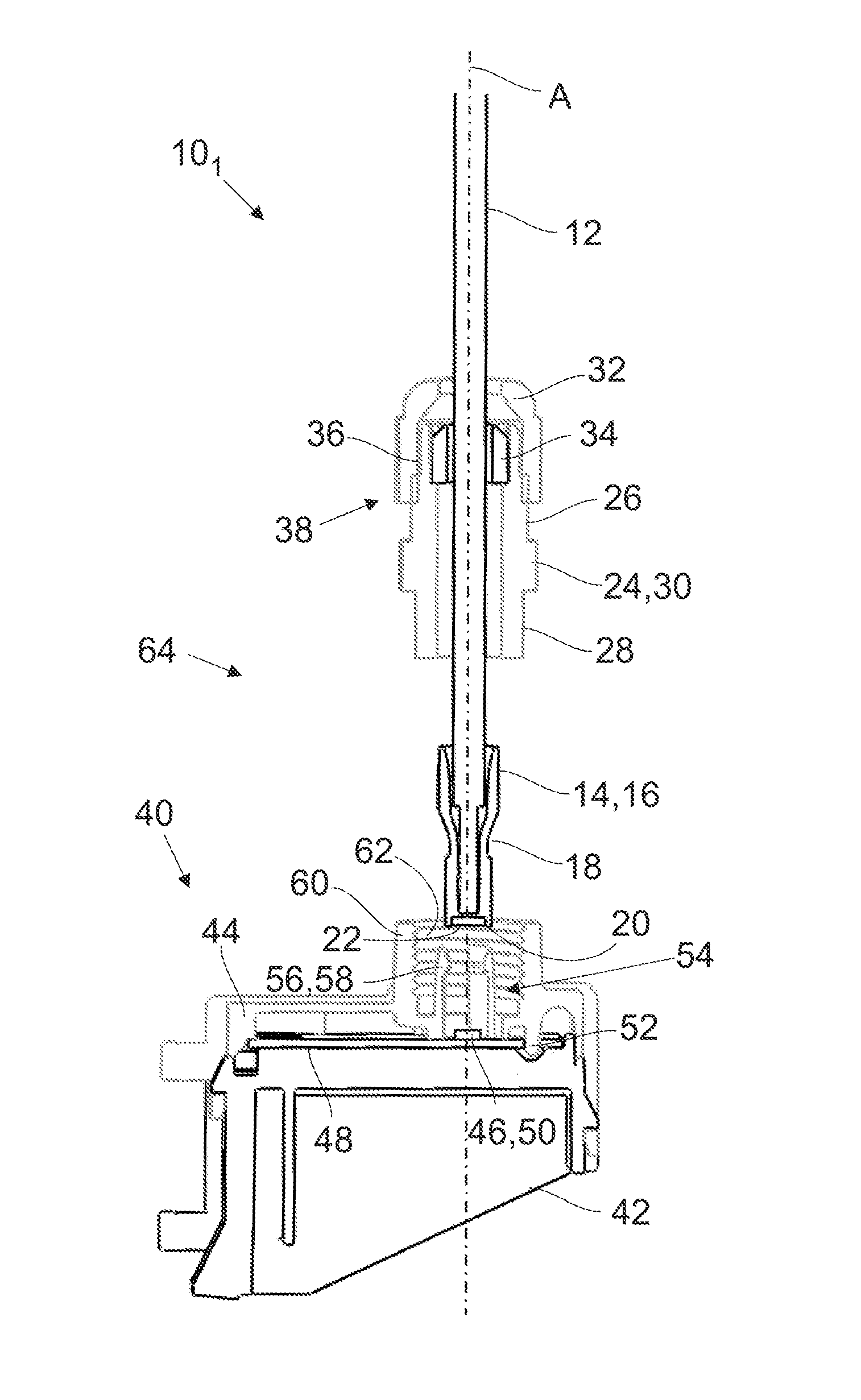
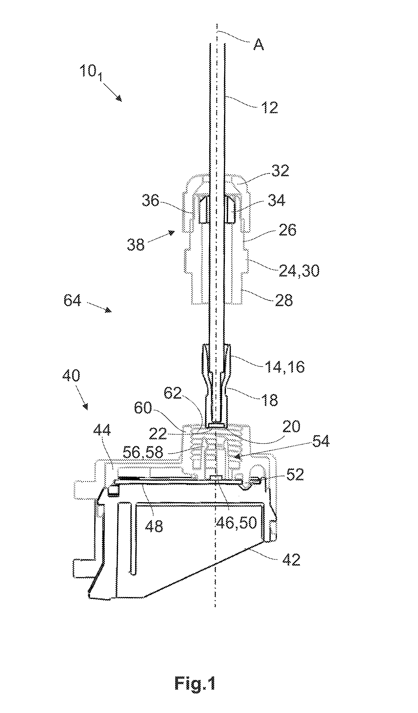
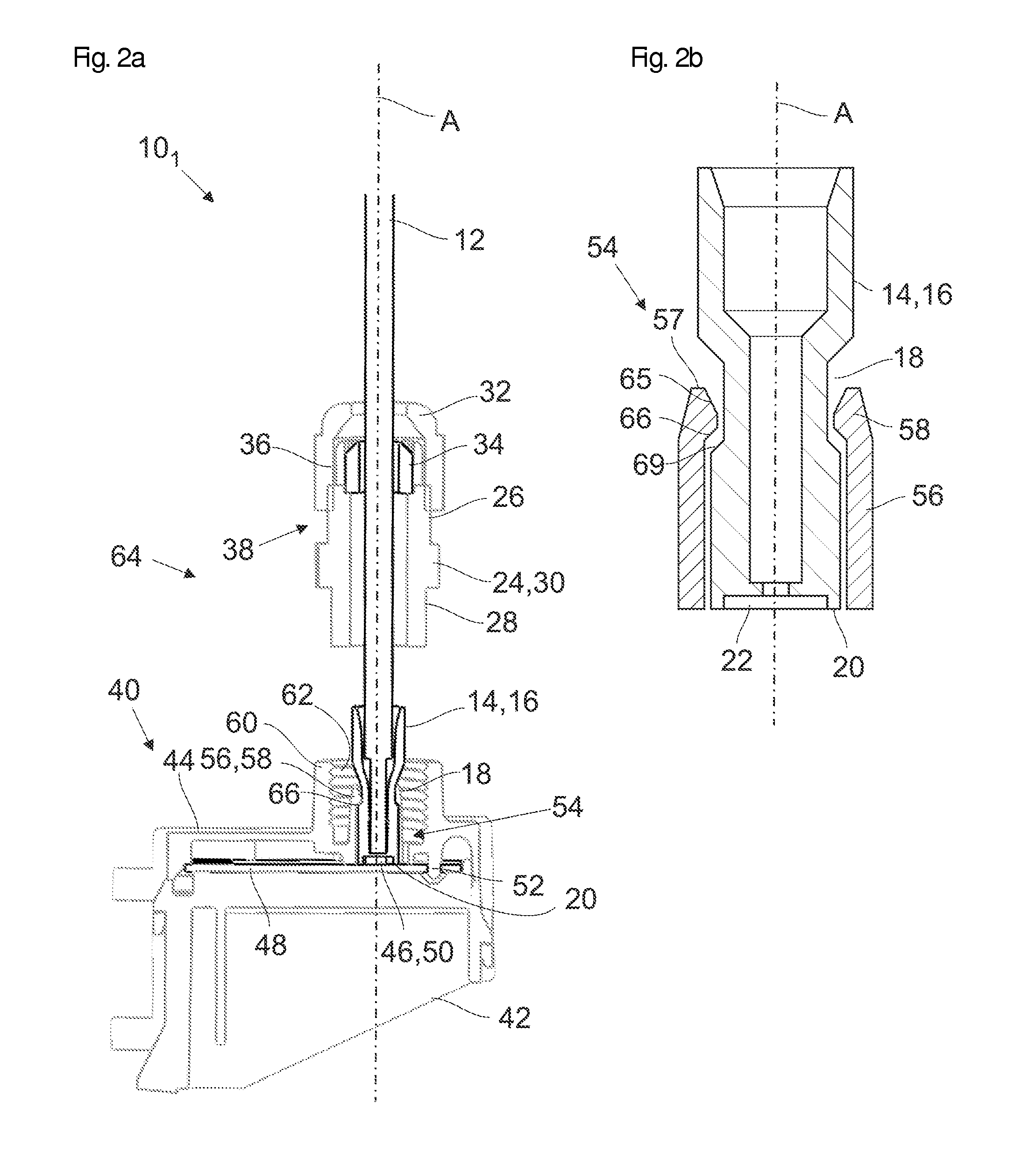
[0044]FIG. 1 shows a cross sectional view of a first exemplary embodiment of the system 101 according to the invention for connecting a fiber optic or rigid light guide to a light source in a disassembled state. The system 101 comprises a fiber optic light guide 12, which is connected to a fiber optic component not shown in detail. Instead of the fiber optic light guide 12 also a rigid light guide 12 may be used. At one end the fiber optic light guide 12 is connected to a ferrule 14, for example by gluing. The ferrule 14 is substantially configured tubular and comprises a contact surface 16 which in the illustrated example corresponds to the outer surface of the ferrule 14. A continuous, annular indentation 18 extends from the contact surface 16. Furthermore, the ferrule 14 comprises an end face 20 from which a recess 22 extends.

[0045]Around the fiber optic light guide 12 a fixing element 24 is displaceably arranged, which in the illustrated example is formed as a tubular sleeve com...


PUM


Abstract

A system and an apparatus for connecting a fiber optic or rigid light guide to a light source are provided. The fiber optic or rigid light guide has one end connected to a ferrule with a contact surface. The system includes a connecting element connectable to the light source, into which the ferrule can be inserted. The connecting element has a number of radially movable fastening portions, wherein the fixing portions are radially biased and cooperate with the contact surface, when the ferrule is inserted into the connecting element, whereby a first retention force is applied to the contact surface, and a fixing element is positioned in such a way that it cooperates with the fastening portions so that a second retention force, which is greater than the first retention force, is applied to the contact surface.

Description

CROSS REFERENCE TO RELATED APPLICATIONS[0001]This application claims benefit under 35 U.S.C. §119(a) of German Patent Application No. 10 2014 217 826.6 filed Sep. 5, 2014, the entire contents of which are incorporated herein by reference.BACKGROUND[0002]1. Field of the Invention[0003]The present invention relates to an apparatus and a method for connecting a fiber optic or rigid light guide to a light source, wherein one end of the fiber optic or rigid light guide is connected to a ferrule which comprises a contact surface.[0004]2. Description of Related Art[0005]Fiber optic or rigid light guides are used to guide light provided by a light source to a fiber optic component even over longer distances, which may be several meters. Fiber optic light guides are described in detail in WO 2009 / 100834 A1. Fiber optic components may be lighting devices of all kinds, which should illuminate an object in any form. At this point lighting devices for vehicles should be mentioned exemplarily, by...

Claims


Application Information

Patent Timeline
Patent Type & Authority Applications(United States)
IPC IPC(8): F21V8/00F21K99/00
CPCF21K9/52G02B6/0006G02B6/4292G02B6/4298
Inventor DIETRICH, ANDREAS
Owner SCHOTT AG
Why Eureka
Try Eureka