Housing for a computing device

a computing device and housing technology, applied in the field of computer systems, can solve the problems of difficult assembly, difficult for users to determine whether proper connection, and not easily located

Inactive Publication Date: 2005-08-23
APPLE INC
View PDF9 Cites 73 Cited by
  • Summary
  • Abstract
  • Description
  • Claims
  • Application Information

AI Technical Summary

Benefits of technology

[0016]As a portable computer housing, one embodiment of the invention includes: a bottom portion providing a bottom surface for said portable computer housing; a top portion providing a top surface for said portable computer housing, said top surface having a palm rest region; and a stiffener affixed to an inner surface of the palm rest region of said top portion. The top portion and said bottom portion are coupled together to form said portable computer housing. The stiffener operates to provide stiffness to the palm rest region substantially beyond the stiffness otherwise provided by said top portion.

Problems solved by technology

One disadvantage with the conventional use of such connectors or slots is that they are not easily located.
Another disadvantage is that it is often difficult for users to determine whether proper connections have been made upon inserting the mating plugs or cards into the connectors or slots.
Unfortunately, the conventional approaches to attaching the touch pad to the base housing lead to problems.
One problem with conventional approaches is that assembly is difficult because the touch pad is assembled and held in place from the inside of the base housing (i.e., from the underside of the palm rest).
Another problem with conventional approaches is that the touch pad is necessarily recessed below the top surface of the palm rest by the thickness of the base housing at the palm rest which tends to make its use by users more difficult.
Also, as base housings get thinner and lighter, the base housings unfortunately get more flexible and thus less stiff.
While internal ridges have been used to increase strength, recent designs are not always amenable to providing for internal ribs.
For example, when there is limited space inside the housing the ribs may not provide the desired stiffness.
As an example, in some of today's portable computers, a deflection of more than ½ millimeter around the CD / DVD drive can damage the sensitive parts of the CD / DVD drive.
The ability of housing to sufficiently resist such deflection is becoming increasingly difficult as base housing become thinner and provide industrial design features.

Method used


Image

  • Housing for a computing device
  • Housing for a computing device
  • Housing for a computing device

Examples


Embodiment Construction

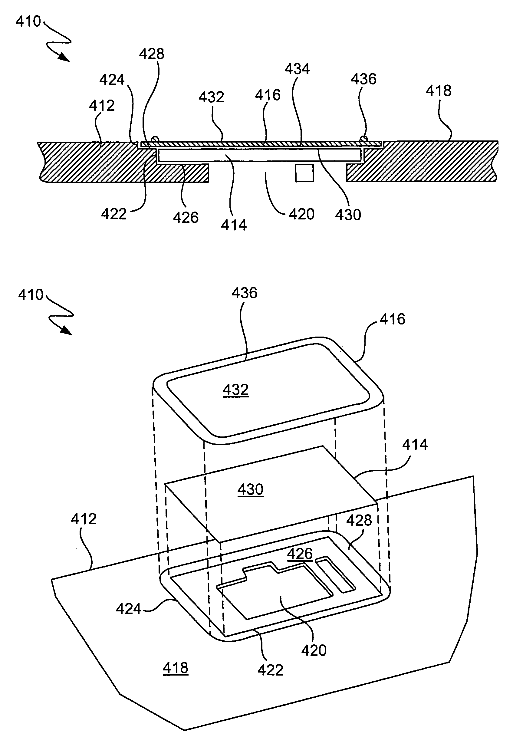
[0026]The invention pertains to an improved housing for a computing device. More particularly, a first aspect of the invention pertains to an illuminable connector suitable for use with the computing device. A second aspect of the invention pertains to a touch pad arrangement also suitable for use with the computing device. Both the illuminable connector and the touch pad arrangement can be provided on external portions of a housing of the computing device such that they are available for user interaction. A third aspect of the invention pertains to a palm rest stiffening plate.

[0027]Embodiments of the invention are discussed below with reference to FIGS. 1–6. However, those skilled in the art will readily appreciate that the detailed description given herein with respect to these figures is for explanatory purposes as the invention extends beyond these limited embodiments.

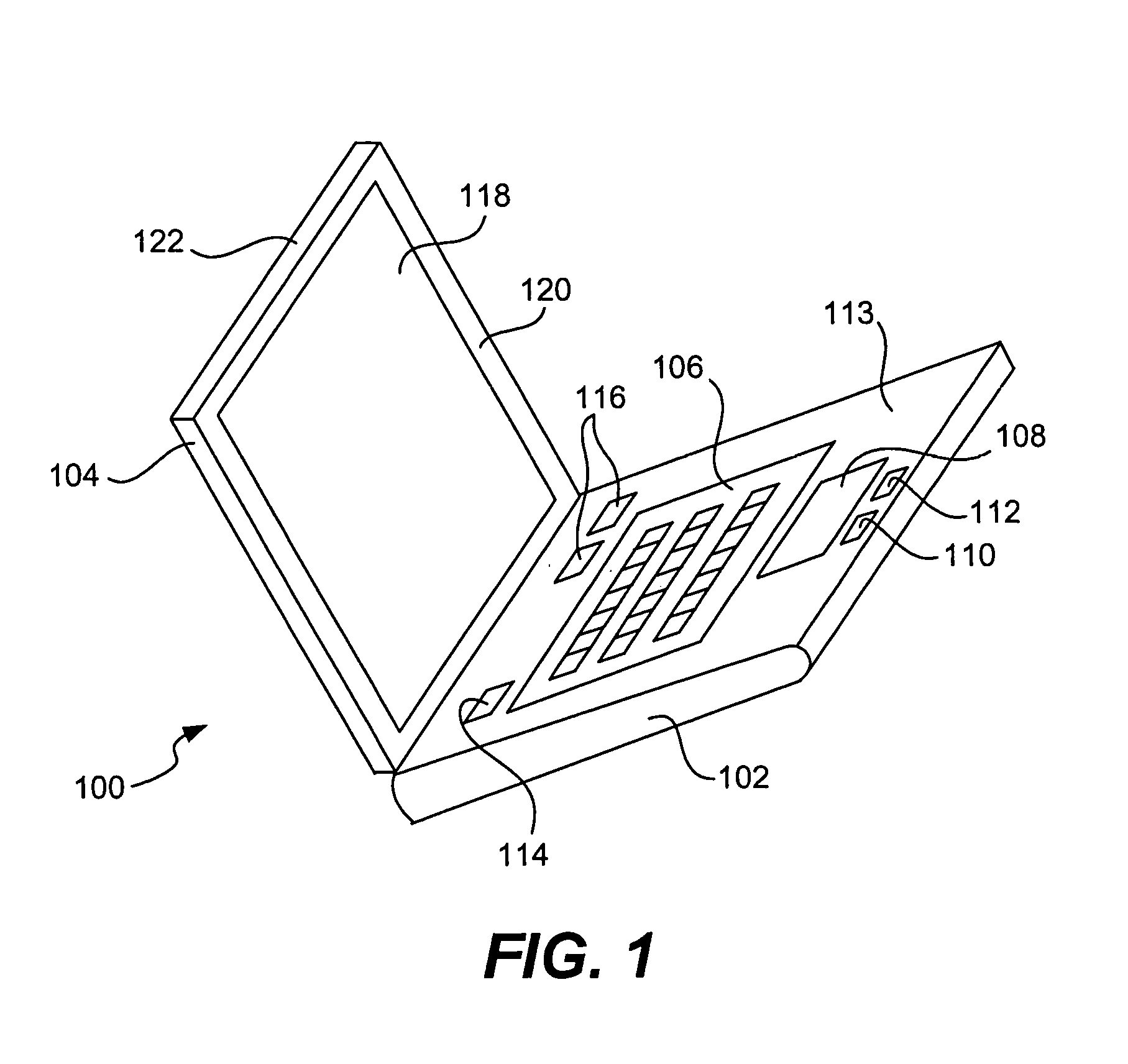
[0028]FIG. 1 is a perspective diagram of a portable computer 100. The portable computer 100 includes a base 102...


PUM


Abstract

Improved housing for a computing device is disclosed. The improved housing is provided with one of an illuminable connector, a touch pad arrangement, and a palm rest stiffening plate. Normally, the illuminable connector and the touch pad arrangement are provided on external portions of a housing of the computing device such that they are available for user interaction. The palm rest stiffening plate is provided internal to a housing to provide stiffness or rigidity to a palm rest region of the housing.

Description

CROSS-REFERENCE TO RELATED APPLICATION[0001]This application claims the benefit of U.S. Provisional Application No. 60 / 134,084, entitled “HOUSING FOR A COMPUTING DEVICE”, and filed on May 14, 1999, the disclosure of which is incorporated herein by reference for all purposes. This application is a divisional of prior U.S. application Ser. No. 09 / 426,408, entitled “DISPLAY HOUSING FOR COMPUTING DEVICE”, filed Oct. 25, 1999 now U.S. Pat. No. 6,357,887.BACKGROUND OF THE INVENTION[0002]1. Field of the Invention[0003]The present invention relates generally to computer system and, more particularly, to improved features for housings of computer systems.[0004]2. Description of the Related Art[0005]All computing devices, including portable computers and desktop computers, have housings that encloses the components and circuitry of the computing devices. These housings are known to include various ports (e.g., parallel port, serial port, audio port, PC-Card slot) at their periphery to allow e...

Claims


Application Information

Patent Timeline
Patent Type & Authority Patents(United States)
IPC IPC(8): G06F1/16
CPCG06F1/1616G06F1/1656G06F1/1684G06F1/169
Inventor NOVAK, CHRIS J.
Owner APPLE INC
Why Eureka
Try Eureka