

Brake mounting bracket apparatus
- Summary
- Abstract
- Description
- Claims
- Application Information
AI Technical Summary
Benefits of technology
Problems solved by technology
Method used
Image

Examples
Embodiment Construction
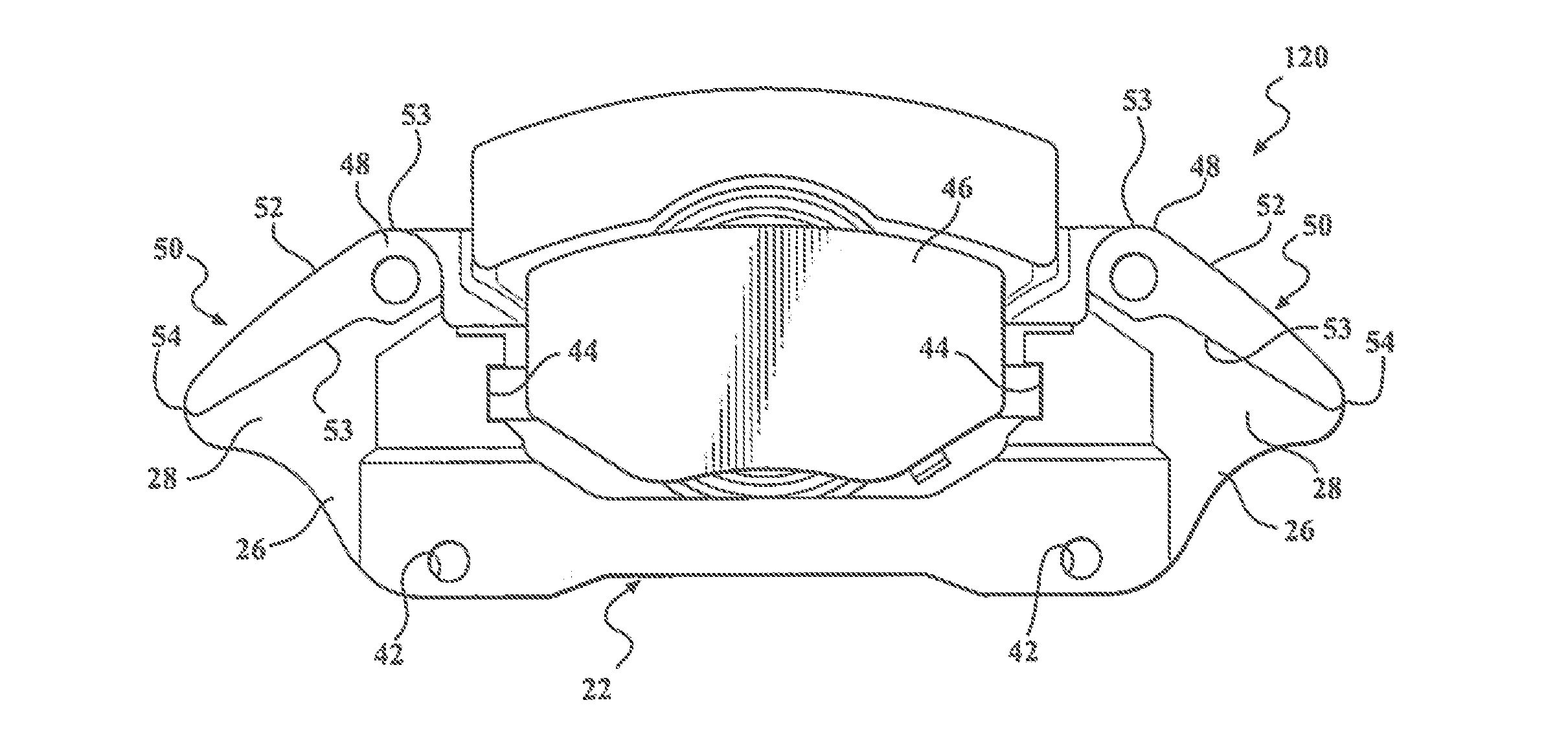
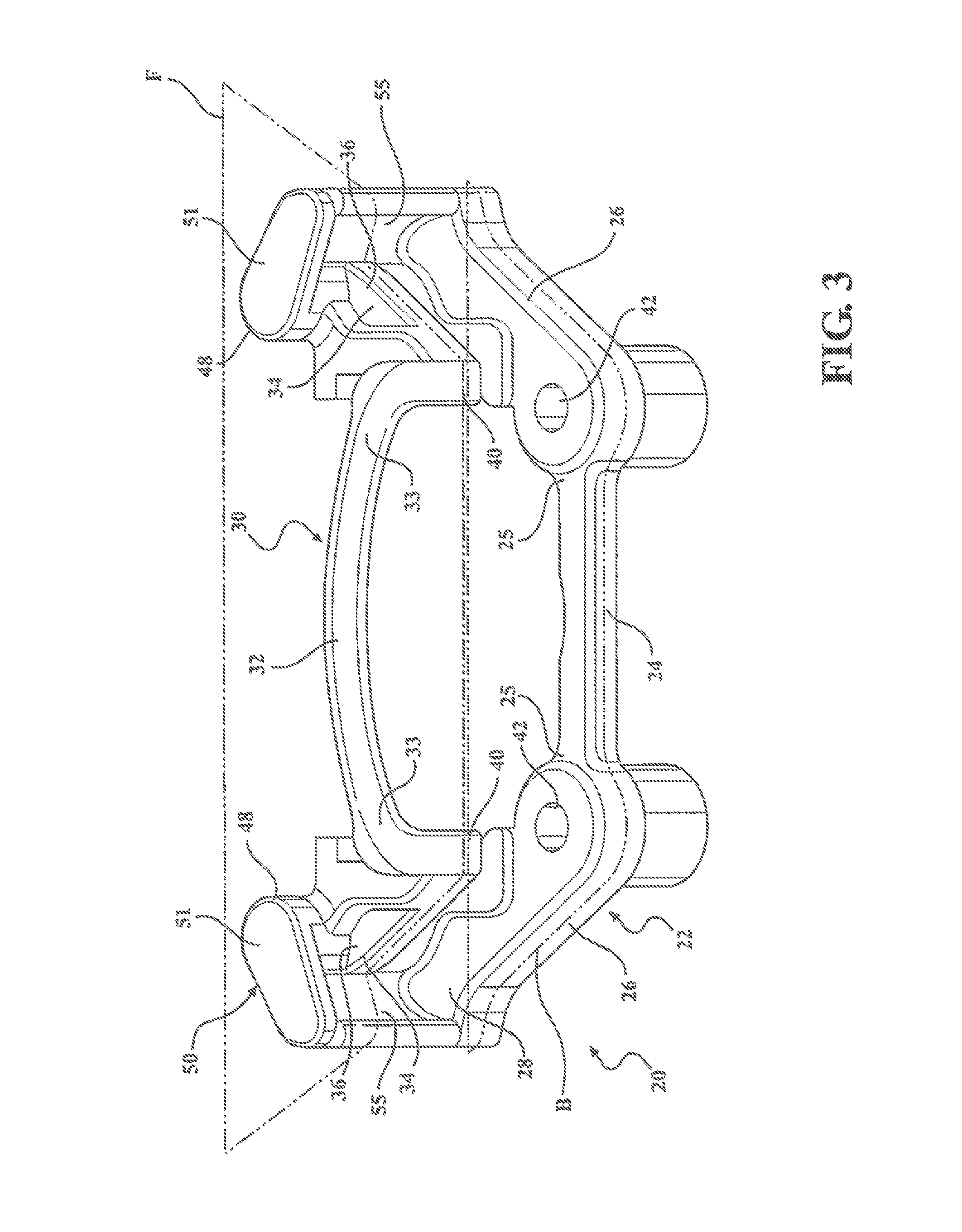
[0025]Referring to the Figures, wherein like numerals indicate corresponding parts throughout the several views, a brake caliper mounting bracket apparatus 20, 120, 220, 320 is generally shown. The brake caliper mounting bracket apparatus 20, 120, 220, 320 includes a rear body 22 that has a generally C-shaped cross-section and extends along a back plane B. The rear body 22 includes an inboard tie bar 24 and a pair of legs 26. The inboard tie bar extends between a pair of margins 25. The pair of legs 26 each extend from one of the margins 25 of the inboard tie bar 24 and diverge away from one another and terminate at an terminal end 28.
[0026]The bracket apparatus further includes a front body 30 that has a generally C-shaped cross-section and extends along a front plane F that is spaced and parallel to the back plane B. The front body 30 includes an outboard tie bar 32 and a pair of arms 34. The outboard tie bar 32 extends between a pair of boundaries 33. The arms 34 each diverge awa...
PUM
 Abstract
Description
Claims
Application Information