Sensor systems

Active Publication Date: 2016-08-04
THE BF GOODRICH CO
View PDF5 Cites 0 Cited by
  • Summary
  • Abstract
  • Description
  • Claims
  • Application Information

AI Technical Summary

Benefits of technology

[0009]In accordance with another aspect, a sensor assembly includes a frame defining a sensor axis having opposing endplates with axially extending supports. The opposing endplates are connected by a pair of axially extending side beams. A sus

Problems solved by technology

One source of sensor LOS destabilizatio

Method used


Image

  • Sensor systems
  • Sensor systems
  • Sensor systems

Examples


Example

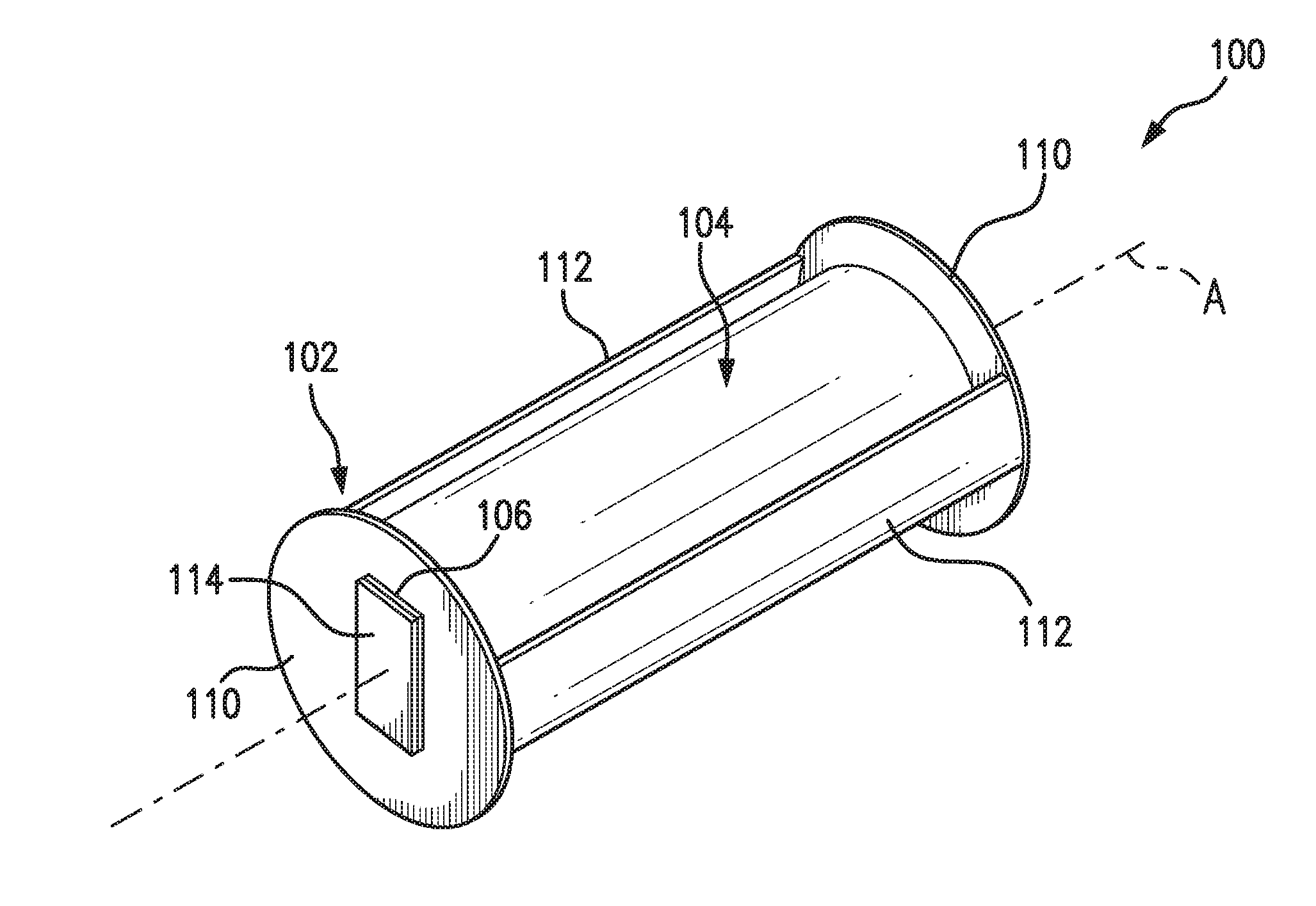
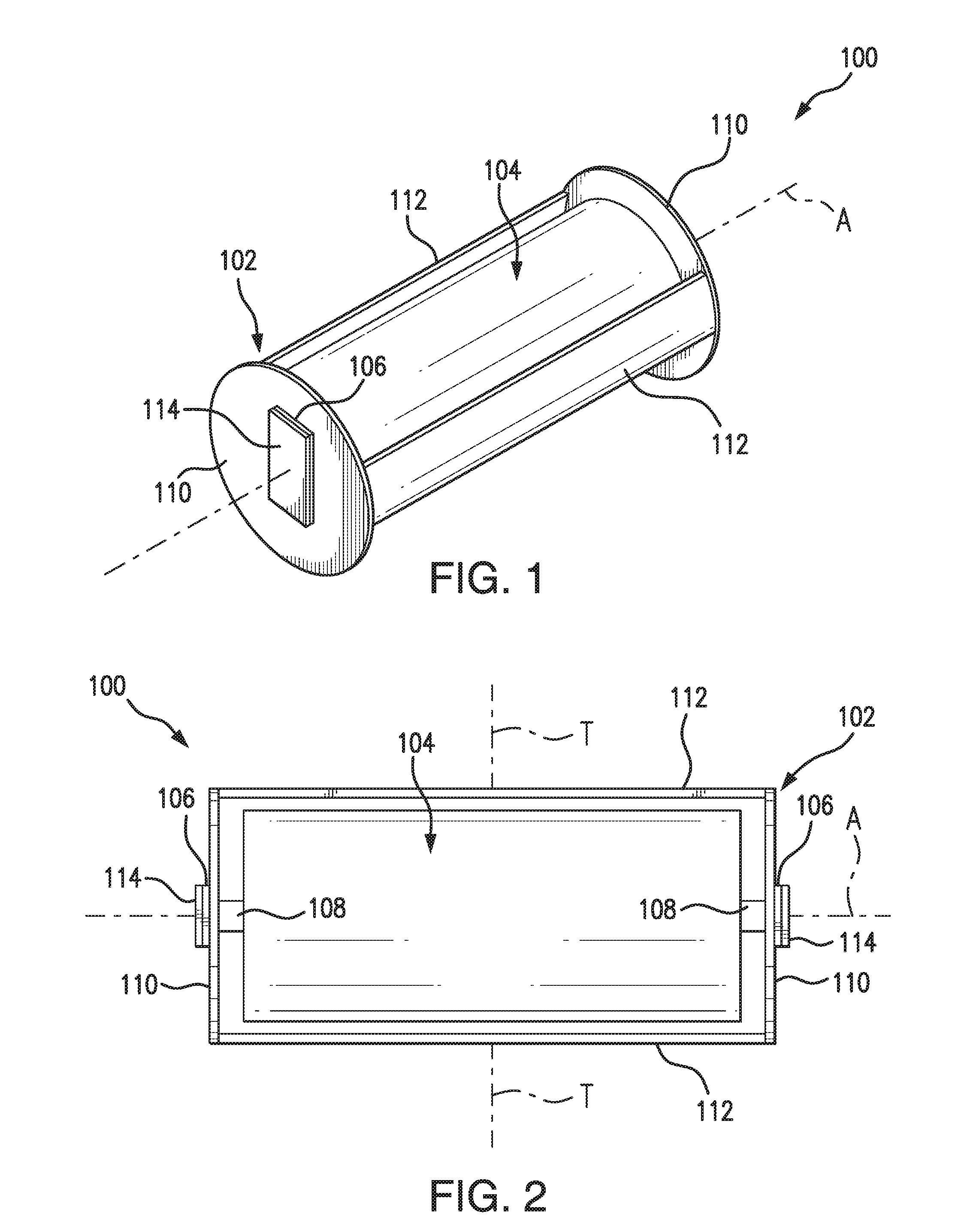
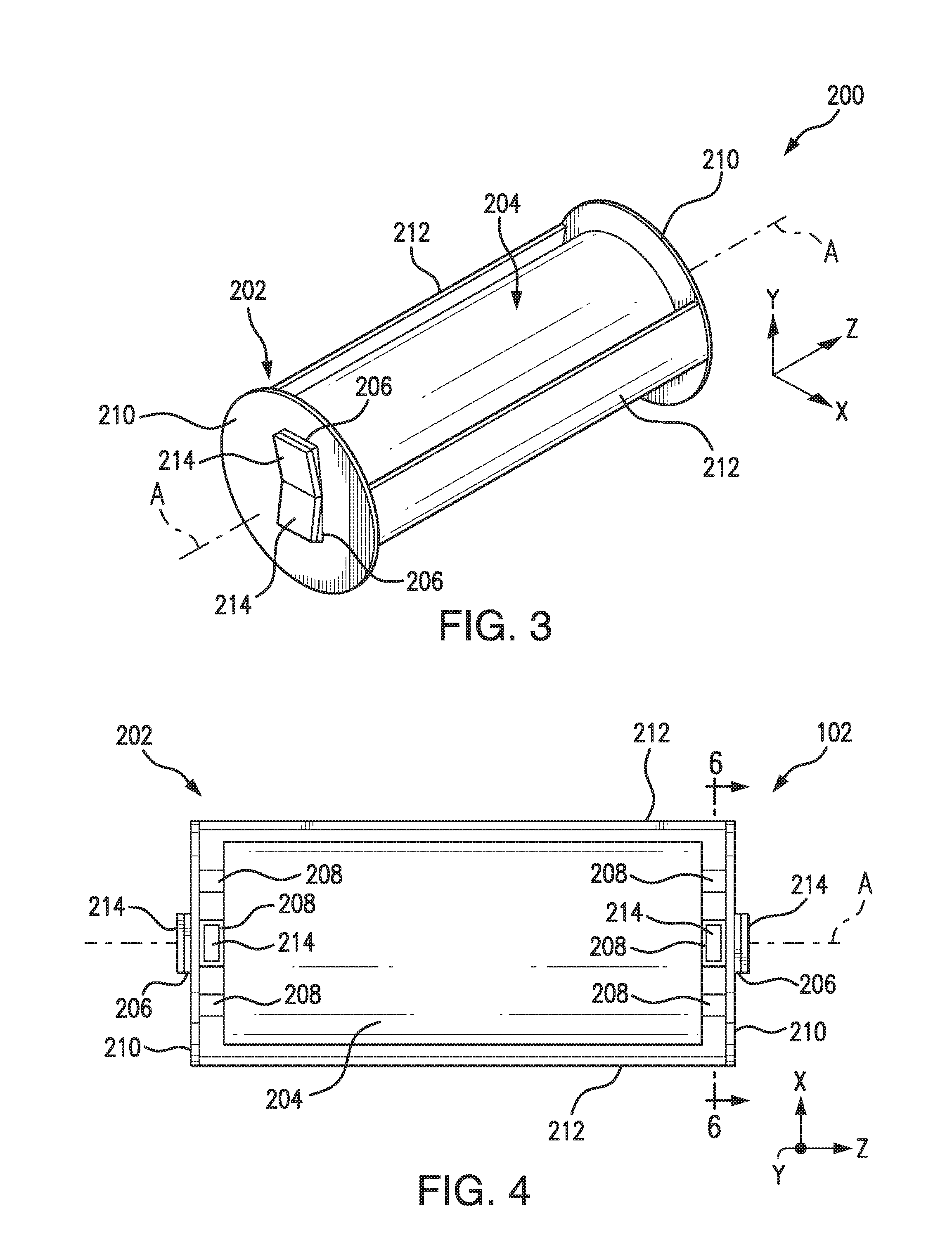
[0023]Reference will now be made to the drawings wherein like reference numerals identify similar structural features or aspects of the subject disclosure. For purposes of explanation and illustration, and not limitation, a partial view of an exemplary embodiment of a sensor assembly constructed in accordance with the disclosure is shown in FIG. 1 and is designated generally by reference character 100. Other embodiments of sensor assemblies in accordance with this disclosure, or aspects thereof, are provided in FIGS. 2-11, as will be described. The systems and methods described herein can be used to reduce vibration experienced by sensor assemblies and reduce the weight of sensor assemblies.

[0024]As shown in FIG. 1, a sensor assembly 100 includes a frame 102, a suspended mass 104 within an interior of frame 102 defining a sensor axis A, and a spacer 106 operatively connected to frame 102. A piezoelectric material layer 114 is operatively connected to a side of spacer 106 opposite of...


PUM


Abstract

A sensor assembly includes a frame defining a sensor axis having opposing endplates with axially extending supports. The opposing endplates are connected by a pair of axially extending side beams. A suspended mass is within an interior of the frame suspended from the supports of the frame. A plurality of piezoelectric material layers are operatively connected to sides of respective spacers opposite the frame to damp vibrations of the suspended mass.

Description

CROSS-REFERENCE TO RELATED APPLICATIONS[0001]This application is a continuation-in-part of U.S. patent application Ser. No. 14 / 612,170 filed Feb. 2, 2015, which is incorporated by reference herein in its entirety.BACKGROUND OF THE INVENTION[0002]1. Field of the Invention[0003]The present disclosure relates to sensor systems, and more particularly to sensor assemblies such as those used in imaging devices.[0004]2. Description of Related Art[0005]A variety of devices and methods are known in the art for sensor systems on aircraft. One parameter that directly affects the quality of many of the images collected by the sensor systems is line-of-sight (LOS) stabilization. One source of sensor LOS destabilization is vibration within the sensor system. Vibrations can be created by environmental influences on the sensor system (e.g. wind drag and turbulence), by operational factors, by platform sources (e.g. aircraft vibrations) and by components within the sensor itself (e.g. fans, heaters,...

Claims


Application Information

Patent Timeline
IPC IPC(8): G01D11/10
CPCG01H11/08G01D11/10G02B27/646
Inventor SMITH, BRIAN J.GILES, ALAN M.
Owner THE BF GOODRICH CO
Why Eureka
Try Eureka