Sample inspection apparatus

Inactive Publication Date: 2006-11-16
OXFORD INSTR NANOTECH TOOLS
View PDF1 Cites 3 Cited by
  • Summary
  • Abstract
  • Description
  • Claims
  • Application Information

AI Technical Summary

Benefits of technology

[0010] Thus, whereas all current techniques for interfacing to a microbeam instrument have concentrated on reducing the power required for cooling devices or attempting to dampen or cancel the vibrations, the invention takes account of the fact that the microbeam instrument, and in particular the stage used for holding samples for inspection, exhibits mechanical resonances at various frequencies.

Problems solved by technology

Any imaging system is sensitive to vibration and when an X-ray detector is interfaced to a microbeam instrument, it is possible for vibration to be transferred to the instrument and adversely affect the quality of images obtained in the imaging mode of the instrument.
Whatever method of cooling is used, some vibration is normally produced.
In addition, vibration may be produced by fans and pumps used in auxiliary systems to take heat away from the main cooler.
While these techniques are helpful, at high magnification there may still be some residual effect on images from the microbeam instrument.
It is very difficult to correct for these during use.
In this case, the cooler is used to cool the sample rather than the X-ray detector transducer but the vibration issues are similar.
Furthermore, where ultra-low temperature refrigeration is required, for example for superconducting magnets used in NMR spectrometry or magnetic resonance imaging (MRI), vibration transferred from the cooler to the instrument may adversely affect performance.

Method used


Image

  • Sample inspection apparatus
  • Sample inspection apparatus
  • Sample inspection apparatus

Examples


Embodiment Construction

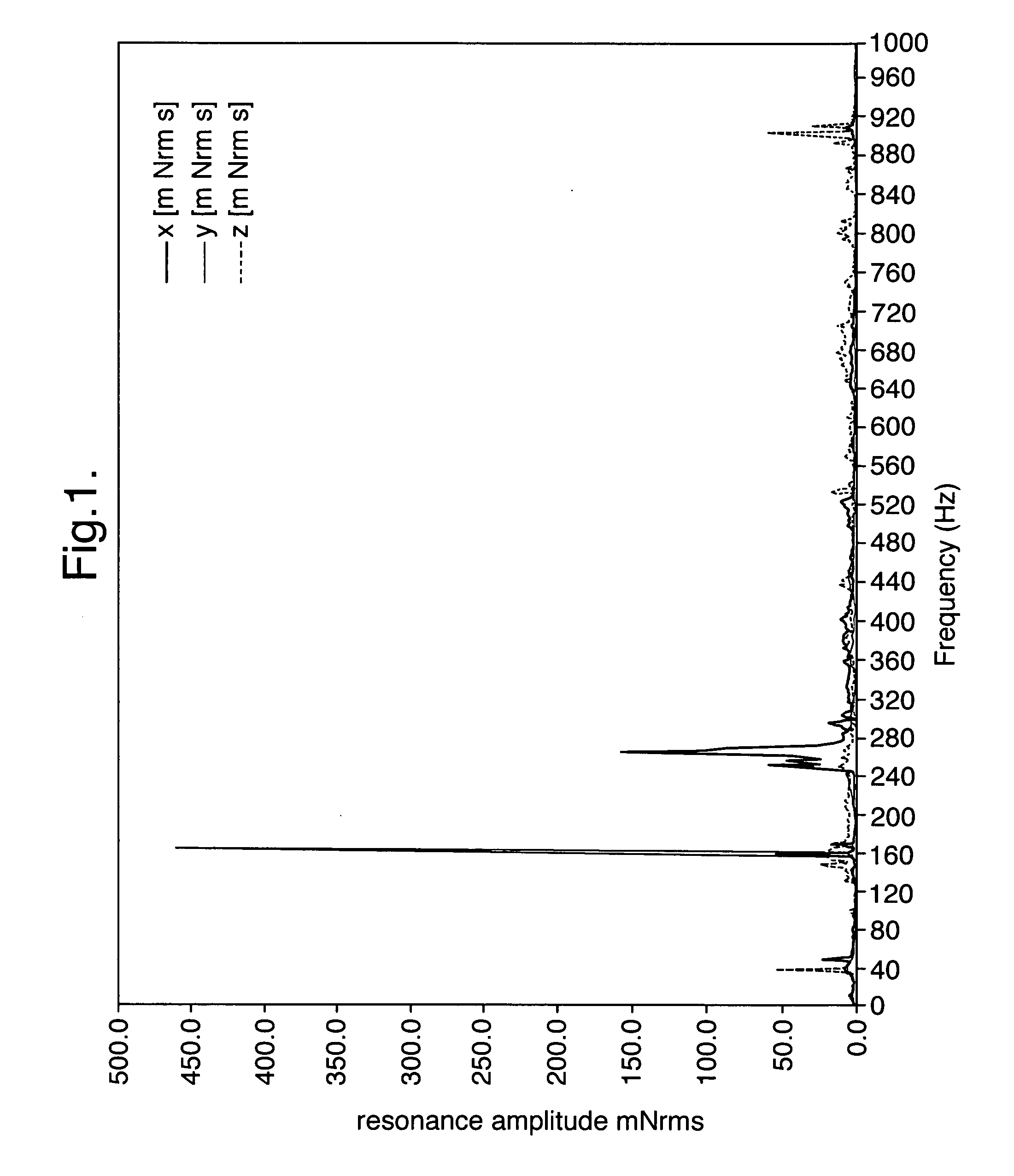
[0026]FIG. 1 shows the amplitude response of a capacitance sensor mounted on a microbeam instrument with an X-ray detector as a function of the frequency of vibration transducer mounted on the chamber wall. The enhanced response at frequencies near 40,160 and 900 Hz in particular suggests the presence of mechanical resonances at these frequencies. If the X-ray detector system includes devices that oscillate at frequencies close to any of these resonances, then vibrations will be more effectively transferred from the X-ray detector to the microbeam instrument. If the X-ray detector system is designed so that the frequency of oscillation can be varied for each oscillating component, then the X-ray detector system can be tuned to minimise the effects of vibration on the microbeam instrument by avoiding such resonances.

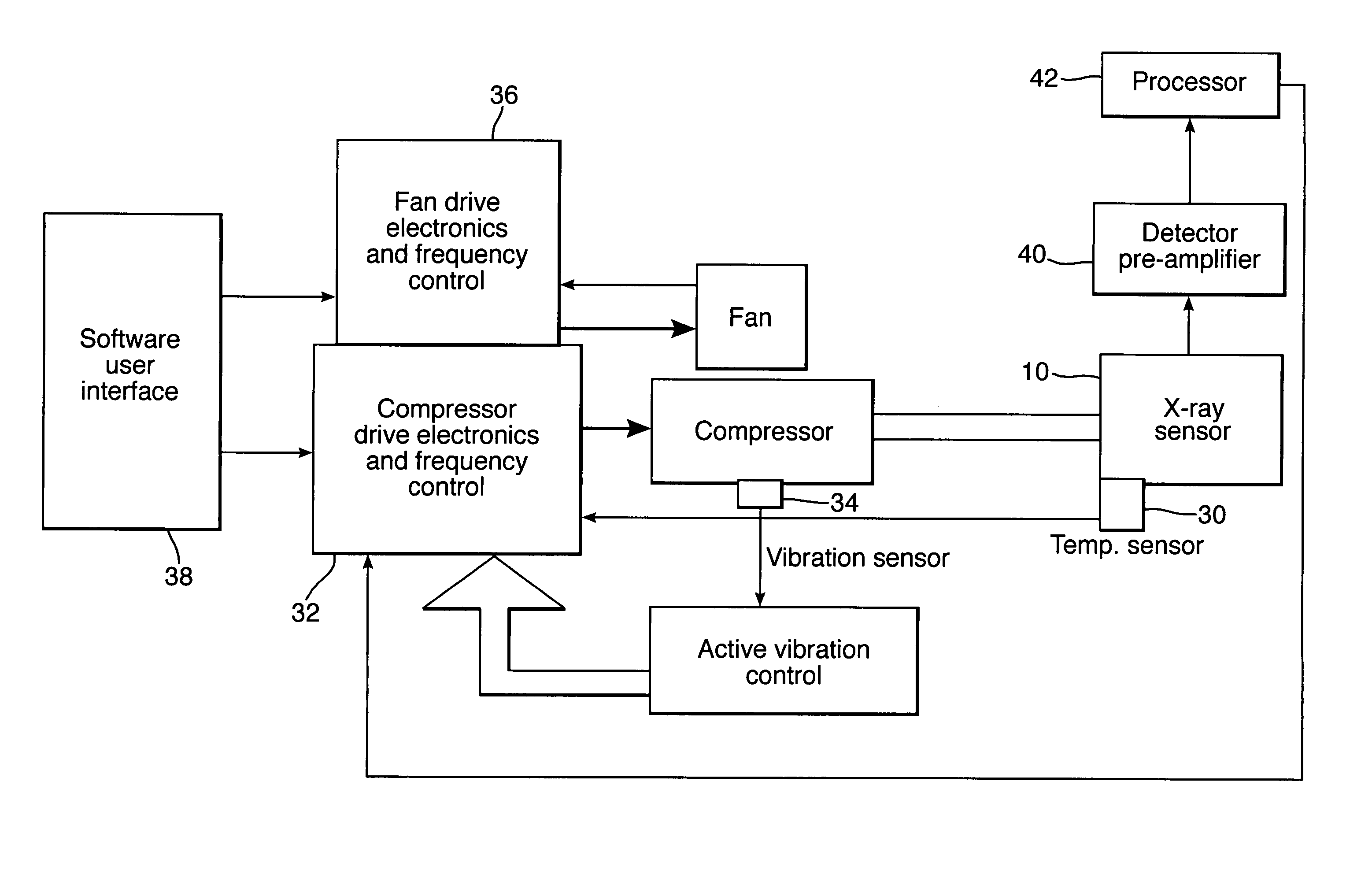
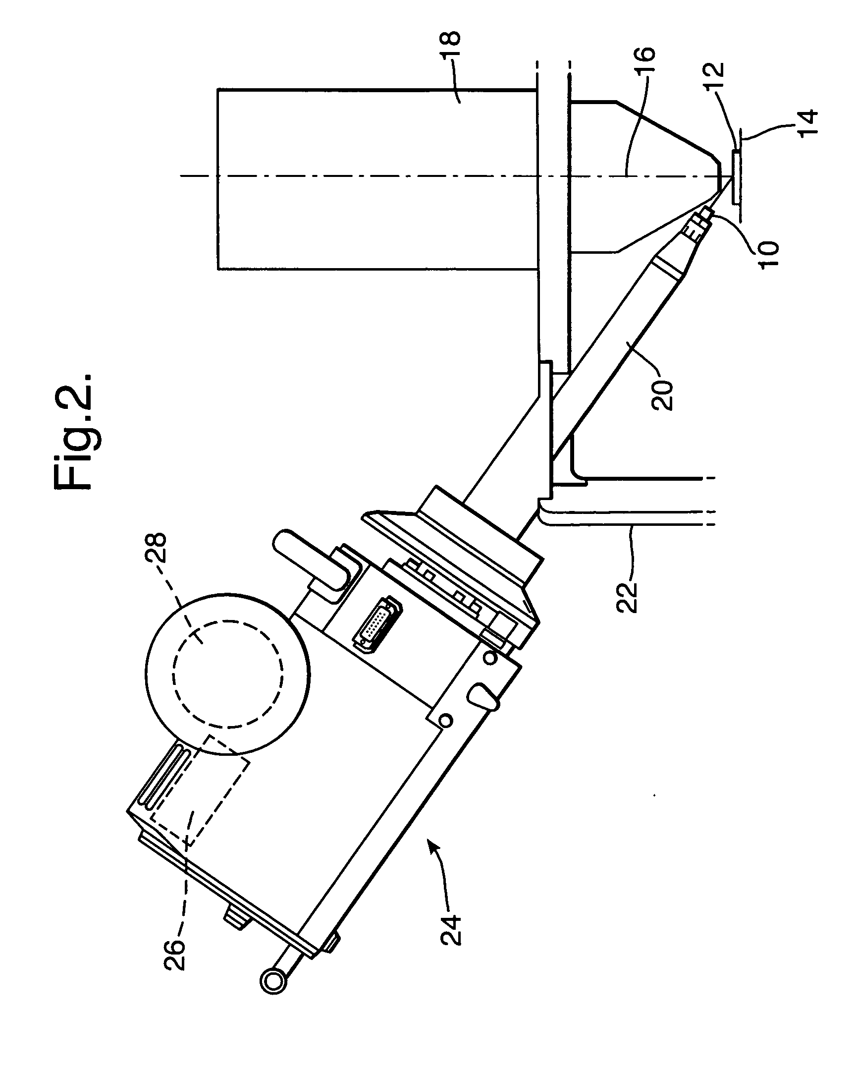
[0027] An example of a microbeam instrument with an X-ray detector which is constructed according to the invention is shown in FIG. 2.

[0028]FIG. 2 illustrates a sample ...


PUM


Abstract

A sample inspection apparatus comprises a sample support; a detection system for detecting radiation emitted by or transmitted through a sample on the sample support in response to radiation incident on the sample; and a cooling system for cooling at least one of the sample support and detection system. The cooling system includes at least one oscillating, mechanical component which oscillates at a frequency different from the at least one of the support and detection system.

Description

FIELD OF THE INVENTION [0001] The invention relates to sample inspection apparatus, for example microbeam instruments that can record images and excite X-rays from a sample. DESCRIPTION OF THE PRIOR ART [0002] Microbeam instruments that can record images and excite x-rays from a sample using an electron beam include scanning electron microscopes (SEMs), transmission electron microscopes (TEMs), scanning transmission electron microscopes (STEMs), electron probe microanalysers (EPMAs) and defect review tools (DRTs). Microbeam instruments are also available that use X-ray optical elements to focus an X-ray beam on a sample and these also now capable of forming images. Any imaging system is sensitive to vibration and when an X-ray detector is interfaced to a microbeam instrument, it is possible for vibration to be transferred to the instrument and adversely affect the quality of images obtained in the imaging mode of the instrument. [0003] In a microbeam instrument, the incident beam of...

Claims


Application Information

Patent Timeline
IPC IPC(8): H01J37/244
CPCH01J37/02H01J2237/2817H01J2237/2001H01J2237/0216
Inventor BHADARE, SANTOKH SINGHBARKSHIRE, IAN RICHARDTURNER, DANIEL FRANK
Owner OXFORD INSTR NANOTECH TOOLS
Why Eureka
Try Eureka