Anti-vibration member and cutting tool

Inactive Publication Date: 2014-04-17
MITSUBISHI HITACHIPOWER SYST LTD
View PDF12 Cites 3 Cited by
  • Summary
  • Abstract
  • Description
  • Claims
  • Application Information

AI Technical Summary

Benefits of technology

[0021]According to the invention, at the time of cutting, the member main body having rubber elasticity or viscoelasticity is deformed due to the deflection and the torsion of the tool, which occur in the tool, and thus vibration of the tool main body can be dampened by a dampening effec

Problems solved by technology

As a cause of degrading the working accuracy of a workpiece at the time of cutting work, there is vibration of a cutting tool during working.
In a case of setting a tool length to be long in order to avoid interference of a c

Method used


Image

  • Anti-vibration member and cutting tool
  • Anti-vibration member and cutting tool
  • Anti-vibration member and cutting tool

Examples


Example

Example 1

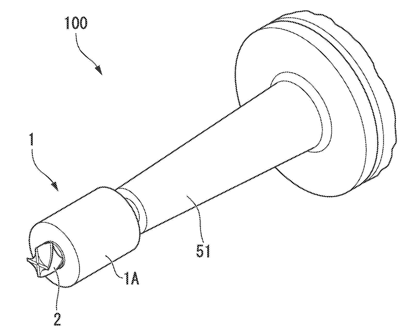
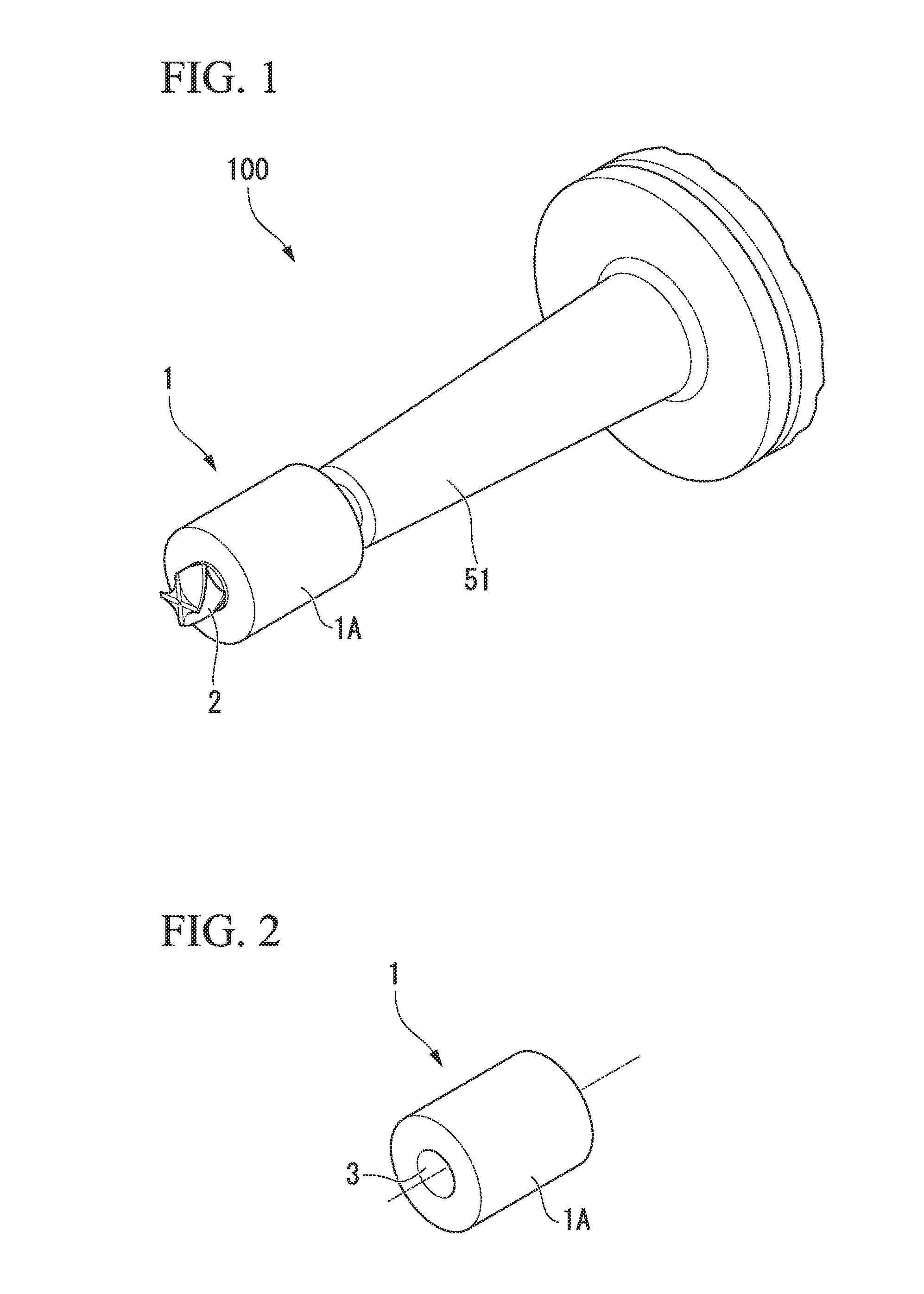
[0057]In Example 1, the test piece was worked on the conditions shown in Table 1 by using an end mill with the anti-vibration member mounted thereon. As for the anti-vibration member, an anti-vibration member having an outer diameter of 40 mm, an inner diameter of 13 mm, and a length of 50 mm was used, and the anti-vibration member was fitted and fixed to an end mill having an outer diameter of 14 mm by interference fit.

Example

Comparative Example 1

[0058]In Comparative Example 1, the test piece was worked on the conditions shown in Table 1 by using an end mill without the anti-vibration member mounted thereon.

[0059]The chipping amounts of the end mills after end faces of the test pieces were subjected to the two-surface working are shown in Table 1. The chipping amount was measured with respect to each of a flank face and a rake face of the end mill. Further, a cutting distance of one surface was set to be about 2.68 m.

[0060]From Table 1, although variation in chipping amount exists in each cutting edge, at the point in time of the two-surface working, a reduction in chipping amount of 49% on average could be confirmed in the evaluation of the flank face. In the evaluation of the rake face, a reduction in chipping amount of 31% on average could be confirmed.

TABLE 1Flank face (mm)Rake face (mm)ComparativeComparativeCutting edgeExample 1Example 1Example 1Example 11-st edge0.0430.0470.0000.0102-nd edge0.0640....

Example

Examples 2-1 and 2-2

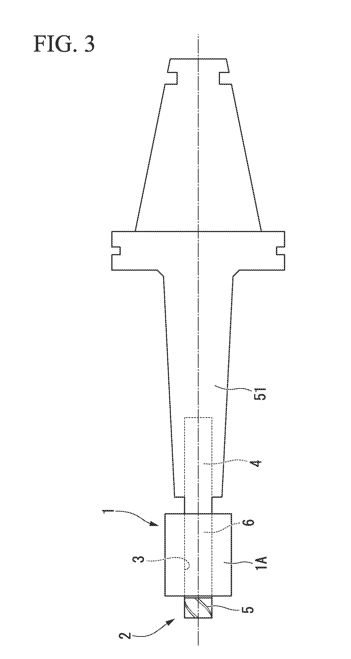
[0063]As Example 2-1, an anti-vibration member covering a shank portion of an end mill over the full length was prepared. As Example 2-2, an anti-vibration member covering about half of a shank portion of an end mill, that is, an anti-vibration member having the full length of about half as compared to Example 2-1 was prepared.


PUM

PropertyMeasurementUnit
Diameteraaaaaaaaaa
Elasticityaaaaaaaaaa
Viscoelasticityaaaaaaaaaa

Abstract

An anti-vibration member is provided which includes a member main body having rubber elasticity or viscoelasticity and can be mounted on an outer surface of a tool main body by a frictional force against the outer surface.

Description

TECHNICAL FIELD[0001]The present invention relates to an anti-vibration member that dampens vibration when mounted on a tool and a cutting tool provided with the anti-vibration member.[0002]Priority is claimed on Japanese Patent Application No. 2011-156602, filed Jul. 15, 2011, the content of which is incorporated herein by reference.BACKGROUND ART[0003]As a cause of degrading the working accuracy of a workpiece at the time of cutting work, there is vibration of a cutting tool during working. In a case of setting a tool length to be long in order to avoid interference of a cutting tool with a workpiece at the time of, for example, milling, it is known that the strength of the cutting tool decreases due to an increase in the protrusion amount of the tool and the occurrence of vibration increases. Due to such circumstances, various attempts have been made in order to suppress vibration of the cutting tool.[0004]For example, in PTL 1, an anti-vibration tool is described in which vibrat...

Claims


Application Information

Patent Timeline
IPC IPC(8): B23Q11/00F16F13/04B23C5/00
CPCB23Q11/0032F16F13/04B23C5/003B23C9/00B23C2226/33B23C2250/16Y10T409/304312
Inventor MATANO, KAZUYAKAWASHITA, RIMPEI
Owner MITSUBISHI HITACHIPOWER SYST LTD
Why Eureka
Try Eureka