Permanent magnet embedded motors, compressors, refrigeration and air conditioning devices

A permanent magnet and motor technology, which is used in the fields of permanent magnet embedded motors, compressors, and refrigeration and air-conditioning devices, can solve the problems of unstable magnetic flux density distribution on the outer peripheral surface of the rotor, vibration, and weakened effects.

Active Publication Date: 2019-06-07
MITSUBISHI ELECTRIC CORP
View PDF6 Cites 0 Cited by
  • Summary
  • Abstract
  • Description
  • Claims
  • Application Information

AI Technical Summary

Problems solved by technology

At this time, the stator magnetic field lines are likely to interlink with the enlarged iron core, and the effect of reducing the magnetic attraction force of the rotor due to the stator magnetic flux is weakened.
[0006] In addition, in the state where the slit thin-walled portion is enlarged so that no slit exists near the outer periphery of the rotor, there is also a concern that the magnetic flux density distribution on the outer peripheral surface of the rotor is unstable, and local magnetic flux tends to be generated in the core portion. Concentration, magnetic attraction due to unbalanced magnetic flux density distribution on the outer peripheral surface of the rotor, which becomes the cause of vibration

Method used


Image

  • Permanent magnet embedded motors, compressors, refrigeration and air conditioning devices
  • Permanent magnet embedded motors, compressors, refrigeration and air conditioning devices
  • Permanent magnet embedded motors, compressors, refrigeration and air conditioning devices

Examples


Embodiment approach 1

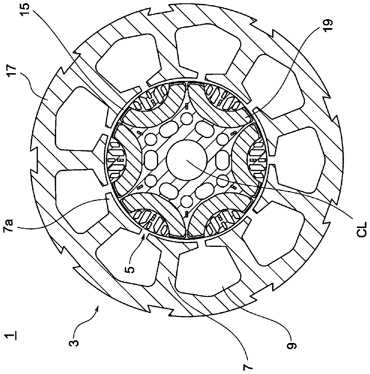
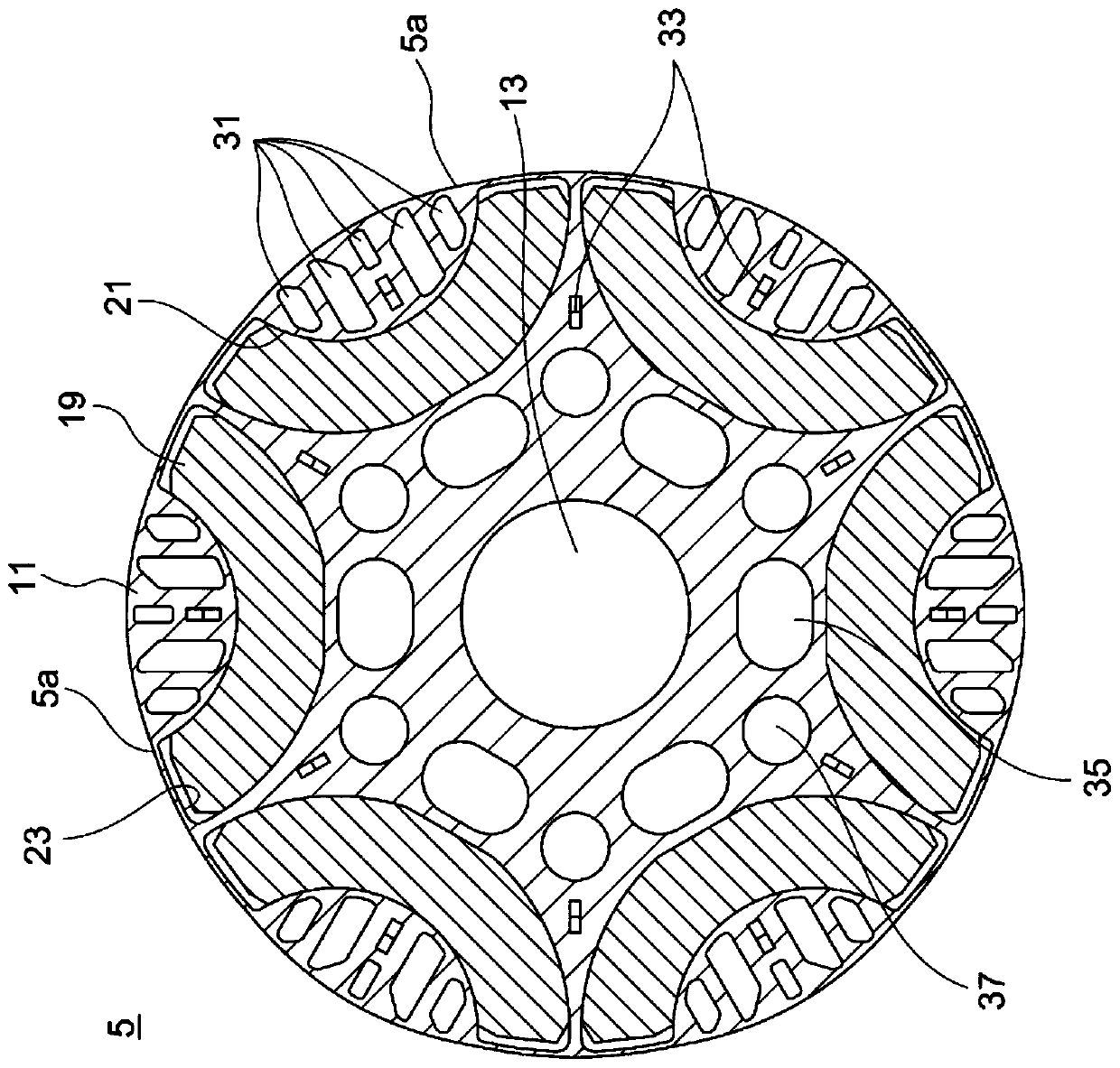
[0027] figure 1 It is a figure which shows the cross section orthogonal to the rotation center line of the permanent magnet embedded motor which concerns on this Embodiment 1. figure 2 is in figure 1 The diagram in which the rotor is enlarged. image 3 is in figure 2 Magnet insertion holes and multiple slits are enlarged in the figure. Figure 4 is in figure 2 The multiple slits are further enlarged and shown in FIG.

[0028] Such as Figure 1 ~ Figure 4 As shown, the permanent magnet embedded motor 1 is provided with the stator 3, and the rotor 5 which opposes the said stator 3 and is provided rotatably. The stator 3 has a plurality of teeth 7 . The plurality of tooth portions 7 are adjacent to other tooth portions 7 via corresponding slot portions 9 . The plurality of tooth portions 7 and the plurality of slot portions 9 are arranged alternately and at equal intervals in the circumferential direction. A well-known stator winding (not shown) is wound around each o...

Embodiment approach 2

[0070] Next, Embodiment 2 of the present invention will be described. Figure 10 is related to the second embodiment, and figure 2 Figures in the same way. However, this second embodiment is the same as the above-mentioned first embodiment except for the parts described below.

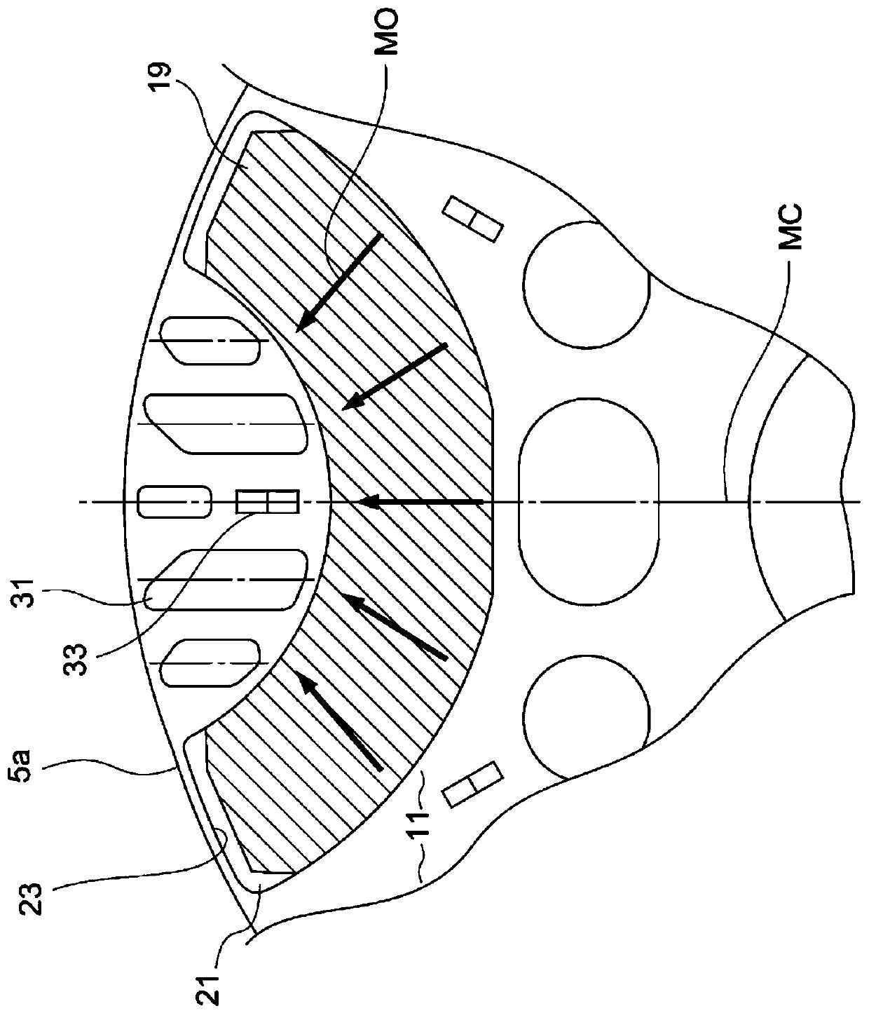
[0071] In the rotor 105 according to Embodiment 2, the ends of the slits 131 on the rotor outer peripheral surface side are chamfered on both sides corresponding to the magnetic pole centerline MC side and the opposite side to the magnetic pole centerline MC. The slit 131 is formed in a shape in which the width of the slit 131 is constant on the side of the magnet insertion hole and narrowed on the side of the rotor outer peripheral surface in the longitudinal direction of the slit 131 .

[0072] With the slit of the above-mentioned shape, the tapered portion (outermost end portion) on the outer peripheral surface side of the rotor is also arranged on the outside with respect to the magnetic pole ce...

Embodiment approach 3

[0074] Next, Embodiment 3 of the present invention will be described. Figure 11 It is related to Embodiment 3 and is a diagram showing the relationship between the rotor and the stator. In addition, this third embodiment is the same as the above-mentioned first or second embodiment except for the parts described below. Also, for ease of illustration, Figure 11 Although the slit of Embodiment 1 was illustrated as an example, it can also be implemented as an example in which the slit of Embodiment 2 is provided.

[0075] The magnetic pole center portion of the rotor outer peripheral surface 5 a bulges radially outward from the interpole portion of the rotor outer peripheral surface 5 a. That is, the rotor outer peripheral surface 5 a has a first arc 51 and a second arc 52 , and the portion on the magnetic pole center line of the first arc 51 bulges most radially outward. Therefore, the air gap between the stator 3 and the interpole portion of the rotor 5 is larger than the ...


PUM


Abstract

A permanent magnet embedded motor (1) includes a rotor (5) having a plurality of permanent magnets (19), and a stator (3) having a rotor core (11) having a plurality of magnet insertion holes (21) A plurality of slits (31) are provided on the radially outer portion of the magnet insertion hole of the rotor core, and at least two slits are provided so that the core portion sandwiched by the two slits faces the radial direction The part that widens on the outside.

Description

technical field [0001] The invention relates to a permanent magnet embedded motor, a compressor, and a refrigerating and air-conditioning device. Background technique [0002] As a conventional embedded permanent magnet motor, for example, Patent Document 1 discloses a structure in which the radial dimension of the thin-walled portion of the slit between each of the plurality of slits and the outer peripheral portion of the rotor core is , making it larger than the radial dimension of the thin-walled portion at the end of the insertion hole between the end gap of the permanent magnet insertion hole and the outer periphery of the rotor core, and making the radial dimension of the thin-walled portion of the slits of the plurality of slits gradually increasing from the interpole toward the pole center, and making the radial dimension of the slit thin-walled portion of the slit closest to the pole center larger than the radial dimension of the slit thin-walled portion of the sli...

Claims


Application Information

Patent Timeline
Patent Type & Authority Patents(China)
IPC IPC(8): H02K21/16
CPCH02K21/16F04C23/008F04C18/356H02K1/2766F04C2210/26F04C2210/263F04C29/0085F04C2240/40F04C18/34H02K1/276
Inventor 仁吾昌弘土田和庆
Owner MITSUBISHI ELECTRIC CORP
Why Eureka
Try Eureka